How to Use SSR DC - DC: Examples, Pinouts, and Specs
Introduction
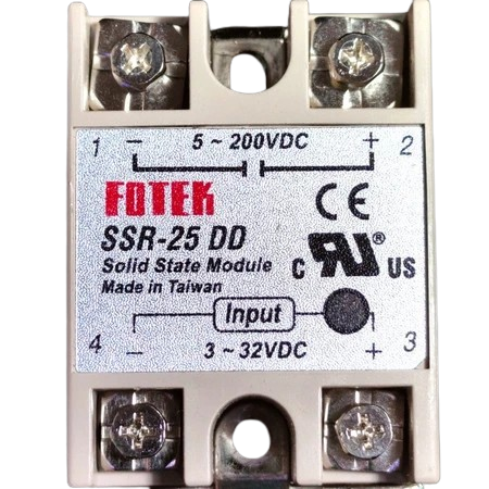
The Fotek SSR DC-DC is a Solid State Relay (SSR) designed specifically for DC applications. It enables the control of high-voltage DC loads using low-voltage control signals. Unlike traditional mechanical relays, the SSR DC-DC offers fast switching, high reliability, and no mechanical wear, making it ideal for applications requiring frequent switching or long operational lifetimes.
Explore Projects Built with SSR DC - DC


Explore Projects Built with SSR DC - DC
Common Applications and Use Cases
- Industrial automation systems
- Motor control in DC circuits
- Battery management systems
- Solar power systems
- LED lighting control
- Robotics and mechatronics
Technical Specifications
The following table outlines the key technical details of the Fotek SSR DC-DC:
| Parameter | Value |
|---|---|
| Manufacturer | Fotek |
| Part ID | Not specified |
| Input Control Voltage | 3-32 V DC |
| Output Voltage Range | 5-220 V DC |
| Maximum Load Current | 40 A |
| Trigger Current | ≤ 7.5 mA |
| On-State Voltage Drop | ≤ 1.5 V |
| Switching Speed | ≤ 10 ms |
| Isolation Voltage | ≥ 2500 V AC |
| Operating Temperature | -30°C to +80°C |
| Storage Temperature | -30°C to +100°C |
| Mounting Type | Panel-mounted |
Pin Configuration and Descriptions
The Fotek SSR DC-DC typically has four terminals, as described in the table below:
| Pin Number | Label | Description |
|---|---|---|
| 1 | + (Input) | Positive terminal for the control signal (3-32 V DC). |
| 2 | - (Input) | Negative terminal for the control signal (ground). |
| 3 | + (Load) | Positive terminal for the DC load. Connect to the positive side of the load. |
| 4 | - (Load) | Negative terminal for the DC load. Connect to the negative side of the load. |
Usage Instructions
How to Use the SSR DC-DC in a Circuit
Control Signal Connection:
- Connect the positive control signal (3-32 V DC) to the
+ (Input)terminal. - Connect the ground of the control signal to the
- (Input)terminal.
- Connect the positive control signal (3-32 V DC) to the
Load Connection:
- Connect the positive side of the DC load to the
+ (Load)terminal. - Connect the negative side of the DC load to the
- (Load)terminal.
- Connect the positive side of the DC load to the
Power Supply:
- Ensure the load voltage and current do not exceed the SSR's rated output voltage (5-220 V DC) and current (40 A).
Mounting:
- Secure the SSR to a heat sink or panel to ensure proper heat dissipation, especially for high-current applications.
Testing:
- Apply the control signal voltage to the input terminals. The SSR should switch the load on or off depending on the presence or absence of the control signal.
Important Considerations and Best Practices
- Heat Dissipation: Use a heat sink or cooling fan to prevent overheating during high-current operation.
- Isolation: Ensure proper electrical isolation between the control and load circuits to avoid damage.
- Polarity: Observe correct polarity for both the control signal and load connections.
- Surge Protection: Use a flyback diode across inductive loads to protect the SSR from voltage spikes.
- Switching Speed: The SSR is not suitable for high-frequency switching applications due to its switching speed limitations.
Example: Connecting the SSR DC-DC to an Arduino UNO
The SSR DC-DC can be controlled using an Arduino UNO. Below is an example circuit and code:
Circuit Description
- Connect the Arduino's digital output pin (e.g., pin 9) to the
+ (Input)terminal of the SSR. - Connect the
- (Input)terminal of the SSR to the Arduino's GND. - Connect the DC load to the
+ (Load)and- (Load)terminals of the SSR. - Ensure the load voltage and current are within the SSR's specifications.
Arduino Code
// Example code to control a Fotek SSR DC-DC with an Arduino UNO
// This code toggles the SSR on and off every 2 seconds.

#define SSR_PIN 9  // Define the Arduino pin connected to the SSR input

void setup() {
  pinMode(SSR_PIN, OUTPUT);  // Set the SSR pin as an output
}

void loop() {
  digitalWrite(SSR_PIN, HIGH);  // Turn the SSR on (load powered)
  delay(2000);                  // Wait for 2 seconds
  digitalWrite(SSR_PIN, LOW);   // Turn the SSR off (load disconnected)
  delay(2000);                  // Wait for 2 seconds
}
Troubleshooting and FAQs
Common Issues and Solutions
| Issue | Possible Cause | Solution |
|---|---|---|
| SSR does not switch the load on or off | Incorrect control signal voltage | Ensure the control signal is within the 3-32 V DC range. |
| Load does not receive power | Incorrect load connections | Verify the polarity and connections of the load terminals. |
| SSR overheats during operation | Insufficient heat dissipation | Attach a heat sink or cooling fan to the SSR. |
| Voltage drop across the SSR is too high | Exceeding the rated load current | Ensure the load current does not exceed 40 A. |
| SSR fails to operate after installation | Damage due to voltage spikes or surges | Use a flyback diode across inductive loads to protect the SSR. |
FAQs
Can the SSR DC-DC be used for AC loads?
- No, this SSR is designed specifically for DC applications. For AC loads, use an AC-AC SSR.
What is the maximum switching frequency of the SSR?
- The SSR has a switching speed of ≤ 10 ms, making it unsuitable for high-frequency switching.
Do I need an external resistor for the control signal?
- No, the SSR has an internal current-limiting circuit for the control signal.
Can I use the SSR without a heat sink?
- For low-current applications, a heat sink may not be necessary. However, for high-current loads, a heat sink is essential to prevent overheating.
How do I protect the SSR from inductive load spikes?
- Use a flyback diode across the load to suppress voltage spikes caused by inductive loads.