Cirkit Designer Logo
Cirkit Designer
Your all-in-one circuit design IDE
Home / 
Component Documentation

How to Use Adafruit JST breakout: Examples, Pinouts, and Specs

Image of Adafruit JST breakout
Cirkit Designer LogoDesign with Adafruit JST breakout in Cirkit Designer

Introduction

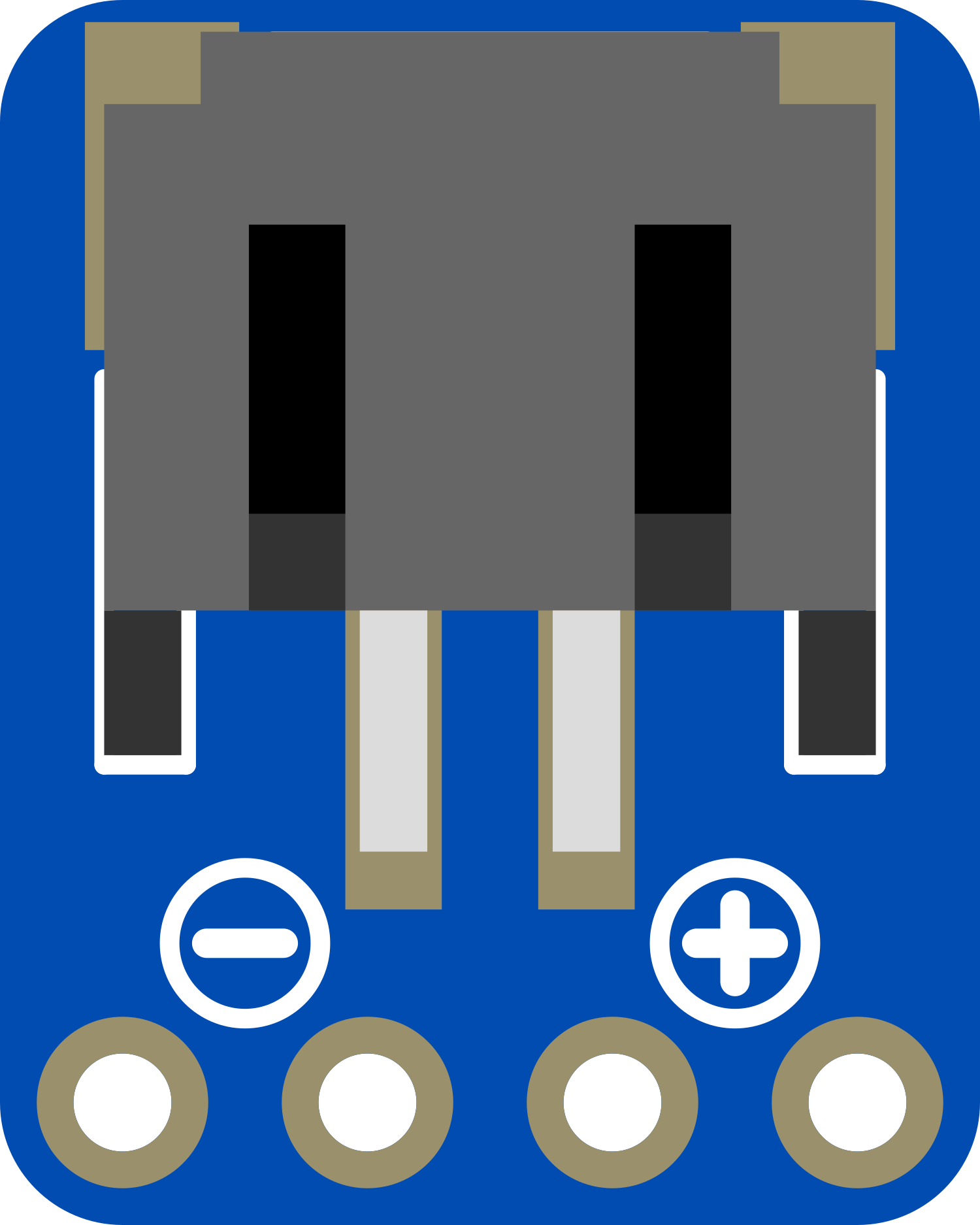
The Adafruit JST Breakout is a versatile and compact circuit board designed to facilitate the use of JST connectors in electronic projects. JST connectors are popular in the electronics industry for their reliability and ease of use in power and data connections. This breakout board is particularly useful for hobbyists and professionals who require a quick and secure method for connecting wires with JST plugs to a prototyping board, such as an Arduino UNO, or directly to other electronic components.

Explore Projects Built with Adafruit JST breakout

Use Cirkit Designer to design, explore, and prototype these projects online. Some projects support real-time simulation. Click "Open Project" to start designing instantly!
Wi-Fi Controlled Environmental Monitoring System with Dual Stepper Motor Valve Actuation
Image of MVP : A project utilizing Adafruit JST breakout in a practical application
This circuit features two 28BYJ-48 stepper motors controlled by ULN2003A breakout boards, interfaced with a NodeMCU V3 ESP8266 microcontroller. The NodeMCU collects environmental data from a DHT11 temperature and humidity sensor and an MQ-135 air quality sensor. The microcontroller uses WiFi for connectivity and controls the stepper motors based on the sensor inputs, likely for regulating environmental conditions.
Cirkit Designer LogoOpen Project in Cirkit Designer
ESP32 CAM Wi-Fi Enabled Camera Module with USB Power
Image of abc: A project utilizing Adafruit JST breakout in a practical application
This circuit consists of an ESP32 CAM module powered by a Micro USB breakout board. The USB breakout board supplies 5V and ground to the ESP32 CAM, enabling it to function and perform tasks such as image capture and processing.
Cirkit Designer LogoOpen Project in Cirkit Designer
ESP32 CAM-Based Impact Detection System with Serial Communication and LED Indicator
Image of esp32 cam: A project utilizing Adafruit JST breakout in a practical application
This circuit features an ESP32 CAM module interfaced with a SparkFun USB UART Breakout for serial communication, allowing the ESP32 to communicate with a computer or other USB host. A BC547 transistor is used to control an LED, with the base driven by one of the ESP32's GPIO pins through a resistor, and multiple piezo sensors are connected to the transistor's emitter, likely for sensing vibrations or impacts. The 5V Adapter provides power to the ESP32 and the LED, while the ground connections are shared among the components.
Cirkit Designer LogoOpen Project in Cirkit Designer
ESP32-Powered NTP Clock with Multiple GC9A01 Displays
Image of InfoOrbsFork: A project utilizing Adafruit JST breakout in a practical application
This circuit features an ESP32 microcontroller connected to multiple GC9A01 displays and a USB Type C breakout for power. The ESP32 runs a sketch to retrieve the current time from an NTP server over WiFi and displays the hours and minutes across the GC9A01 displays, with each display showing a single digit or colon separator. Pushbuttons are connected to GPIOs on the ESP32, potentially for user input to control display functions or settings.
Cirkit Designer LogoOpen Project in Cirkit Designer

Explore Projects Built with Adafruit JST breakout

Use Cirkit Designer to design, explore, and prototype these projects online. Some projects support real-time simulation. Click "Open Project" to start designing instantly!
Image of MVP : A project utilizing Adafruit JST breakout in a practical application
Wi-Fi Controlled Environmental Monitoring System with Dual Stepper Motor Valve Actuation
This circuit features two 28BYJ-48 stepper motors controlled by ULN2003A breakout boards, interfaced with a NodeMCU V3 ESP8266 microcontroller. The NodeMCU collects environmental data from a DHT11 temperature and humidity sensor and an MQ-135 air quality sensor. The microcontroller uses WiFi for connectivity and controls the stepper motors based on the sensor inputs, likely for regulating environmental conditions.
Cirkit Designer LogoOpen Project in Cirkit Designer
Image of abc: A project utilizing Adafruit JST breakout in a practical application
ESP32 CAM Wi-Fi Enabled Camera Module with USB Power
This circuit consists of an ESP32 CAM module powered by a Micro USB breakout board. The USB breakout board supplies 5V and ground to the ESP32 CAM, enabling it to function and perform tasks such as image capture and processing.
Cirkit Designer LogoOpen Project in Cirkit Designer
Image of esp32 cam: A project utilizing Adafruit JST breakout in a practical application
ESP32 CAM-Based Impact Detection System with Serial Communication and LED Indicator
This circuit features an ESP32 CAM module interfaced with a SparkFun USB UART Breakout for serial communication, allowing the ESP32 to communicate with a computer or other USB host. A BC547 transistor is used to control an LED, with the base driven by one of the ESP32's GPIO pins through a resistor, and multiple piezo sensors are connected to the transistor's emitter, likely for sensing vibrations or impacts. The 5V Adapter provides power to the ESP32 and the LED, while the ground connections are shared among the components.
Cirkit Designer LogoOpen Project in Cirkit Designer
Image of InfoOrbsFork: A project utilizing Adafruit JST breakout in a practical application
ESP32-Powered NTP Clock with Multiple GC9A01 Displays
This circuit features an ESP32 microcontroller connected to multiple GC9A01 displays and a USB Type C breakout for power. The ESP32 runs a sketch to retrieve the current time from an NTP server over WiFi and displays the hours and minutes across the GC9A01 displays, with each display showing a single digit or colon separator. Pushbuttons are connected to GPIOs on the ESP32, potentially for user input to control display functions or settings.
Cirkit Designer LogoOpen Project in Cirkit Designer

Common Applications and Use Cases

  • Battery connections for small robotics, drones, or RC vehicles
  • Power supply connections for portable electronics
  • Signal connections for sensors and modules
  • Prototyping with devices that use JST connectors for interfacing

Technical Specifications

Key Technical Details

  • Voltage Rating: Typically 0-12V (refer to specific JST connector rating)
  • Current Rating: Up to 2A (depending on the JST connector used)
  • Connector Type: JST PH 2.0mm or similar (verify with product specifics)
  • Dimensions: Varies by model (check datasheet for exact size)

Pin Configuration and Descriptions

Pin Number Description Notes
1 VCC (Power Supply) Connect to positive power rail
2 GND (Ground) Connect to ground
3-n Signal/Data Lines As per JST connector pin count

Note: The actual pinout may vary based on the JST connector type used on the breakout board. Always refer to the manufacturer's datasheet for the exact pin configuration.

Usage Instructions

How to Use the Component in a Circuit

  1. Identify the JST Connector: Determine the type of JST connector on your breakout board and the corresponding cable.
  2. Connect the JST Cable: Plug the JST cable into the breakout board, ensuring a secure fit.
  3. Wiring: Solder wires to the breakout board's through-hole or surface-mount pads, depending on the design. Connect these wires to your circuit, respecting the correct polarity and signal assignments.
  4. Mounting: Secure the breakout board to your project using screws or adhesive, if mounting holes or pads are provided.

Important Considerations and Best Practices

  • Polarity: Always check the polarity of the connections to prevent damage to the breakout board and other components.
  • Current Limit: Do not exceed the current rating of the JST connector to avoid overheating and potential failure.
  • Secure Connections: Ensure that all soldered connections are solid and that the JST cable is firmly seated to prevent intermittent connections.
  • Isolation: If the breakout board is being used in a high-vibration environment, consider using hot glue or a similar method to reinforce the JST cable connection.

Troubleshooting and FAQs

Common Issues Users Might Face

  • Loose Connections: If the breakout board is not functioning as expected, check all connections for looseness or poor solder joints.
  • Incorrect Polarity: Reversed polarity can lead to non-functioning circuits or damage. Double-check the wiring against the breakout board's pinout.
  • Exceeding Current Rating: If the breakout board overheats, ensure that the current draw is within the specified limits.

Solutions and Tips for Troubleshooting

  • Resolder Connections: If a connection is loose, resolder it to ensure a solid electrical contact.
  • Polarity Check: Use a multimeter to verify the polarity of the power supply and connections.
  • Current Measurement: Use a multimeter to measure the current draw and ensure it does not exceed the breakout board's rating.

FAQs

Q: Can I use this breakout board with any JST connector? A: The breakout board is designed for specific JST connector types. Verify compatibility with your JST connector before use.

Q: What wire gauge should I use with the breakout board? A: The wire gauge should be appropriate for the current rating of the JST connector and the breakout board. Typically, 22-28 AWG wires are suitable for most applications.

Q: Is it possible to daisy-chain multiple breakout boards? A: Yes, as long as the total current draw does not exceed the rating of the individual JST connectors and the power supply capacity.

Example Code for Arduino UNO

// Example code to demonstrate how to use the Adafruit JST Breakout with an Arduino UNO
// This example assumes a JST-connected sensor with an analog output

const int sensorPin = A0; // Connect the sensor's signal wire to analog pin A0

void setup() {
  Serial.begin(9600); // Start serial communication at 9600 baud rate
}

void loop() {
  int sensorValue = analogRead(sensorPin); // Read the value from the sensor
  Serial.println(sensorValue); // Print the sensor value to the serial monitor
  delay(500); // Wait for half a second before reading the value again
}

Note: The above code is a simple example to read an analog value from a sensor connected via the Adafruit JST Breakout. Modify the code as needed for your specific application and sensor type.

Remember to consult the datasheet and technical resources provided by Adafruit for the most accurate and detailed information regarding the Adafruit JST Breakout board.