How to Use HDR-15-5 5V 2.4A: Examples, Pinouts, and Specs
Introduction
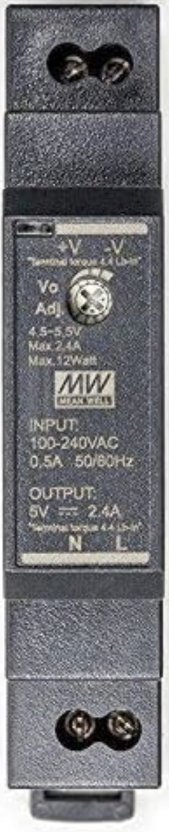
The HDR-15-5 is a compact, high-efficiency power supply module manufactured by Mean Well. It is designed to provide a stable 5V DC output with a maximum current of 2.4A, making it ideal for powering a wide range of electronic devices and circuits. Its slim DIN-rail mountable design ensures easy integration into industrial control panels, home automation systems, and other applications where space is limited.
Explore Projects Built with HDR-15-5 5V 2.4A


Explore Projects Built with HDR-15-5 5V 2.4A
Common Applications and Use Cases
- Industrial control systems
- Home automation and IoT devices
- Embedded systems and microcontroller projects
- LED lighting and signage
- General-purpose DC power supply for electronic circuits
Technical Specifications
The HDR-15-5 is designed to meet the needs of modern electronic systems with high efficiency and reliability. Below are its key technical specifications:
| Parameter | Value |
|---|---|
| Manufacturer | Mean Well |
| Part Number | HDR-15-5 |
| Input Voltage Range | 85-264 VAC / 120-370 VDC |
| Output Voltage | 5V DC |
| Maximum Output Current | 2.4A |
| Output Power | 12W |
| Efficiency | Up to 83% |
| Operating Temperature | -30°C to +70°C |
| Dimensions | 17.5 x 90 x 54.5 mm (W x H x D) |
| Mounting Type | DIN-rail (TS-35/7.5 or TS-35/15) |
| Protection Features | Overload, overvoltage, short circuit |
| Certifications | UL, CE, EAC, RoHS |
Pin Configuration and Descriptions
The HDR-15-5 features screw terminal connections for input and output. Below is the pin configuration:
| Pin | Label | Description |
|---|---|---|
| 1 | L | AC Line Input |
| 2 | N | AC Neutral Input |
| 3 | -V | DC Output Negative (Ground) |
| 4 | +V | DC Output Positive (5V) |
Usage Instructions
The HDR-15-5 is straightforward to use in a variety of applications. Follow the steps below to integrate it into your circuit:
Step 1: Mounting the Power Supply
- Secure the HDR-15-5 onto a DIN rail (TS-35/7.5 or TS-35/15) in your control panel or enclosure.
- Ensure the power supply is mounted in a well-ventilated area to prevent overheating.
Step 2: Connecting the Input
- Connect the AC line (L) and neutral (N) wires to the input terminals of the HDR-15-5.
- Ensure the input voltage is within the specified range (85-264 VAC).
Step 3: Connecting the Output
- Connect the +V terminal to the positive rail of your circuit.
- Connect the -V terminal to the ground rail of your circuit.
- Verify that the connected load does not exceed the maximum output current of 2.4A.
Step 4: Powering On
- After all connections are secure, power on the AC input.
- Use a multimeter to verify the output voltage is 5V DC before connecting sensitive devices.
Important Considerations and Best Practices
- Load Regulation: Ensure the connected load is within the power supply's rated capacity to avoid triggering overload protection.
- Ventilation: Maintain adequate airflow around the power supply to prevent overheating.
- Safety: Always disconnect the AC input before making any wiring changes.
- Polarity: Double-check the polarity of the output connections to avoid damaging connected devices.
Example: Using HDR-15-5 with an Arduino UNO
The HDR-15-5 can be used to power an Arduino UNO and other peripherals. Below is an example wiring setup:
- Connect the +V terminal of the HDR-15-5 to the Arduino's 5V pin.
- Connect the -V terminal of the HDR-15-5 to the Arduino's GND pin.
- Ensure the total current draw of the Arduino and peripherals does not exceed 2.4A.
Here is a simple Arduino sketch to blink an LED when powered by the HDR-15-5:
// Blink an LED connected to pin 13
// Ensure the HDR-15-5 is providing a stable 5V to the Arduino UNO

void setup() {
  pinMode(13, OUTPUT); // Set pin 13 as an output
}

void loop() {
  digitalWrite(13, HIGH); // Turn the LED on
  delay(1000);            // Wait for 1 second
  digitalWrite(13, LOW);  // Turn the LED off
  delay(1000);            // Wait for 1 second
}
Troubleshooting and FAQs
Common Issues and Solutions
No Output Voltage
- Cause: Input AC voltage is not connected or is out of range.
- Solution: Verify the AC input connections and ensure the voltage is within 85-264 VAC.
Overload Protection Triggered
- Cause: The connected load exceeds the maximum output current of 2.4A.
- Solution: Reduce the load to within the rated capacity.
Overheating
- Cause: Insufficient ventilation or operation in a high-temperature environment.
- Solution: Improve airflow around the power supply and ensure ambient temperature is within -30°C to +70°C.
Output Voltage Fluctuations
- Cause: Unstable input voltage or excessive load changes.
- Solution: Stabilize the input voltage and avoid rapid load changes.
FAQs
Q1: Can the HDR-15-5 be used with DC input?
A1: Yes, the HDR-15-5 supports DC input in the range of 120-370 VDC.
Q2: Is the HDR-15-5 suitable for outdoor use?
A2: No, the HDR-15-5 is not weatherproof and should only be used in indoor environments.
Q3: What happens if the load exceeds 2.4A?
A3: The power supply's overload protection will activate, shutting down the output to protect the device.
Q4: Can I use the HDR-15-5 to charge batteries?
A4: The HDR-15-5 is not designed for direct battery charging. Use a dedicated battery charger for this purpose.
By following this documentation, you can safely and effectively use the HDR-15-5 in your projects.