How to Use Busbar: Examples, Pinouts, and Specs
Introduction
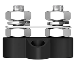
A busbar is a conductive material, typically made of copper or aluminum, designed to distribute electrical power efficiently across multiple circuits or devices within a system. Manufactured by Joinfworld, this component serves as a central hub for connecting various electrical components, enabling streamlined power distribution and management.
Busbars are widely used in electrical panels, power distribution systems, and industrial applications where high current handling and reliability are critical. Their compact design and ability to reduce wiring complexity make them an essential component in modern electrical systems.
Explore Projects Built with Busbar


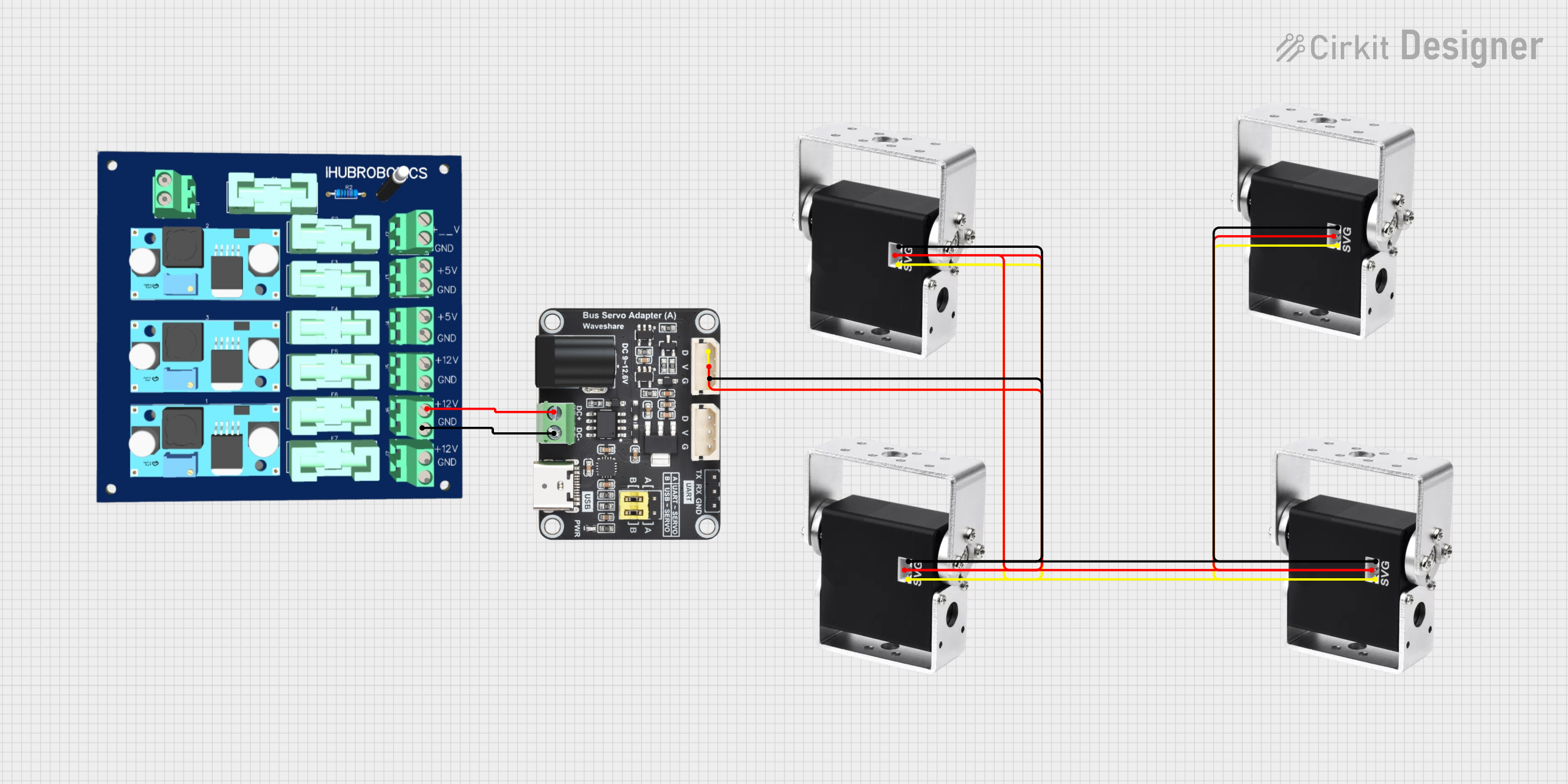

Explore Projects Built with Busbar
Common Applications
- Electrical switchgear and control panels
- Power distribution in industrial and commercial buildings
- Renewable energy systems (e.g., solar and wind power installations)
- Automotive and electric vehicle power systems
- Data centers and server racks
Technical Specifications
Below are the key technical details for the Joinfworld Busbar:
General Specifications
| Parameter | Value |
|---|---|
| Material | Copper or Aluminum |
| Current Rating | Up to 1000 A (varies by model) |
| Voltage Rating | Up to 1000 V AC/DC |
| Operating Temperature | -40°C to +120°C |
| Insulation Resistance | ≥ 10 MΩ |
| Surface Finish | Tin-plated or bare metal |
| Dimensions | Customizable (length, width, thickness) |
Pin Configuration and Descriptions
Busbars do not have traditional "pins" like ICs or connectors. Instead, they feature connection points or terminals for attaching wires, lugs, or other components. Below is a general description of the connection points:
| Connection Point | Description |
|---|---|
| Terminal 1 | Input power connection |
| Terminal 2 | Output power connection to load or circuit |
| Mounting Holes | Used to secure the busbar to a panel or chassis |
Usage Instructions
How to Use the Busbar in a Circuit
Determine the Current and Voltage Requirements:
- Ensure the busbar's current and voltage ratings meet or exceed the system's requirements.
- Select the appropriate material (copper for high conductivity, aluminum for cost efficiency).
Mount the Busbar:
- Secure the busbar to a non-conductive surface using the provided mounting holes.
- Ensure proper insulation to prevent accidental short circuits.
Connect the Power Source:
- Attach the input power cable to the designated terminal using a lug or clamp.
- Tighten the connection securely to minimize resistance and heat generation.
Distribute Power to Loads:
- Connect the output terminals to the desired circuits or devices.
- Use appropriate wire sizes to handle the expected current.
Inspect Connections:
- Verify all connections are tight and free of corrosion.
- Use a multimeter to check for continuity and proper voltage levels.
Important Considerations and Best Practices
- Avoid Overloading: Do not exceed the busbar's current or voltage ratings, as this can lead to overheating and potential failure.
- Ensure Proper Insulation: Use insulating covers or barriers to prevent accidental contact with live parts.
- Minimize Voltage Drop: Keep the busbar length as short as possible to reduce resistance and voltage drop.
- Regular Maintenance: Periodically inspect the busbar for signs of wear, corrosion, or loose connections.
Example: Connecting a Busbar to an Arduino UNO
While busbars are not directly connected to microcontrollers like the Arduino UNO, they can be used in power distribution systems that supply power to the Arduino and other devices. Below is an example of how to integrate a busbar into such a system:
// Example: Powering an Arduino UNO using a busbar
// This setup assumes a 12V power source connected to the busbar,
// with a step-down converter providing 5V to the Arduino UNO.

#include <Arduino.h>

void setup() {
  // Initialize the Arduino (no specific busbar code is required)
  Serial.begin(9600);
  Serial.println("Arduino powered via busbar system.");
}

void loop() {
  // Example loop to demonstrate functionality
  Serial.println("System running...");
  delay(1000);
}

/*
Wiring Notes:
- Connect the 12V power source to the busbar's input terminal.
- Use a step-down converter to reduce 12V to 5V for the Arduino UNO.
- Connect the step-down converter's output to the Arduino's 5V and GND pins.
- Ensure all connections are secure and insulated to prevent short circuits.
*/
Troubleshooting and FAQs
Common Issues and Solutions
| Issue | Possible Cause | Solution |
|---|---|---|
| Overheating of the busbar | Exceeding current rating | Reduce load or use a higher-rated busbar. |
| Loose connections | Improper tightening of terminals | Re-tighten connections securely. |
| Corrosion on terminals | Exposure to moisture or contaminants | Clean terminals and apply anti-corrosion grease. |
| Voltage drop across the busbar | Excessive length or undersized busbar | Use a shorter or thicker busbar. |
FAQs
Can I use a busbar for both AC and DC systems?
- Yes, busbars are suitable for both AC and DC power distribution, provided their ratings match the system requirements.
What is the difference between copper and aluminum busbars?
- Copper busbars offer higher conductivity and durability but are more expensive. Aluminum busbars are lighter and more cost-effective but have slightly lower conductivity.
How do I calculate the required busbar size?
- Use the formula:
Cross-sectional Area (mm²) = Current (A) / Current Density (A/mm²). Consult manufacturer guidelines for recommended current densities.
- Use the formula:
Do I need to insulate the busbar?
- Yes, insulation is essential to prevent accidental contact and short circuits. Use insulating covers or barriers as needed.
By following this documentation, you can effectively integrate the Joinfworld Busbar into your electrical systems for reliable and efficient power distribution.