
How to Use PICAXE-18M: Examples, Pinouts, and Specs
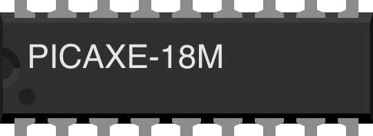
 Design with PICAXE-18M in Cirkit Designer
Introduction
The PICAXE-18M, manufactured by Revolution Education Ltd, is an 8-bit microcontroller designed for educational and hobbyist applications. It is part of the PICAXE family, which is known for its ease of use and built-in programming capabilities. The PICAXE-18M is ideal for beginners and advanced users alike, offering a versatile platform for learning microcontroller programming and building electronic projects.
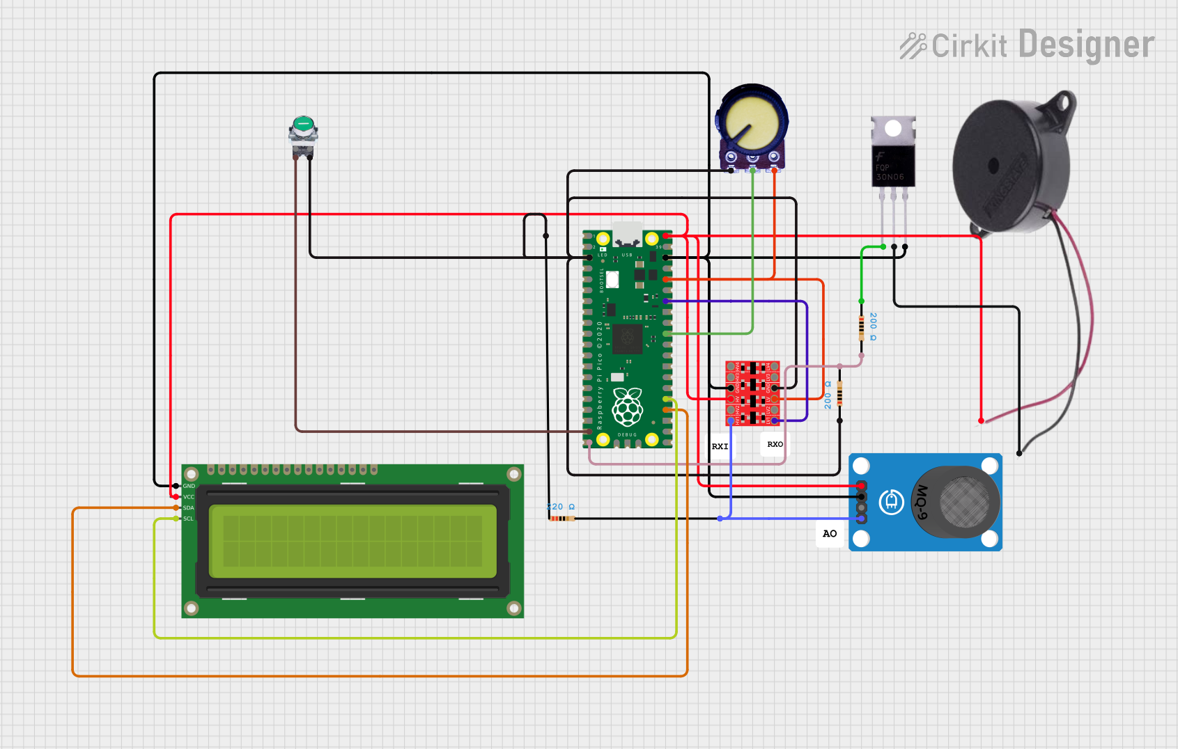
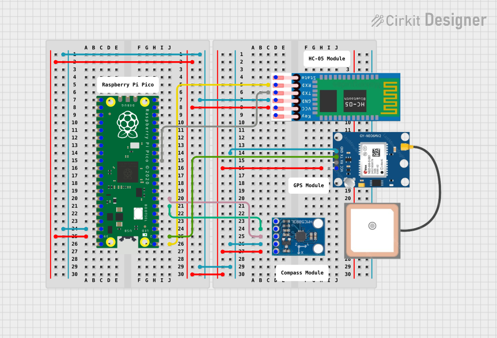
Explore Projects Built with PICAXE-18M
 Open Project in Cirkit Designer
 Open Project in Cirkit Designer
 Open Project in Cirkit Designer
 Open Project in Cirkit Designer
Explore Projects Built with PICAXE-18M
Open Project in Cirkit DesignerOpen Project in Cirkit DesignerOpen Project in Cirkit DesignerOpen Project in Cirkit DesignerCommon Applications and Use Cases
- Educational projects for learning microcontroller programming
- Hobbyist electronics and DIY projects
- Sensor interfacing and data acquisition
- Simple robotics and automation systems
- LED control and display systems
Technical Specifications
The following table outlines the key technical details of the PICAXE-18M microcontroller:
| Parameter | Specification |
|---|---|
| Architecture | 8-bit |
| Operating Voltage | 3V to 5.5V |
| Clock Speed | 4 MHz (internal resonator) |
| Programming Language | PICAXE BASIC |
| Flash Memory | 2048 bytes |
| RAM | 128 bytes |
| EEPROM | 256 bytes |
| I/O Pins | 5 digital inputs, 8 digital outputs |
| ADC Channels | 4 (10-bit resolution) |
| Communication Protocols | Serial (via programming cable) |
| Package Type | 18-pin DIP |
Pin Configuration and Descriptions
The PICAXE-18M has an 18-pin DIP package. The pin configuration and their functions are detailed below:
| Pin Number | Pin Name | Function |
|---|---|---|
| 1 | VSS | Ground |
| 2 | Serial In | Serial programming input |
| 3 | Serial Out | Serial programming output |
| 4 | ADC1 | Analog input channel 1 / Digital input |
| 5 | ADC2 | Analog input channel 2 / Digital input |
| 6 | ADC3 | Analog input channel 3 / Digital input |
| 7 | ADC4 | Analog input channel 4 / Digital input |
| 8 | Output 0 | Digital output |
| 9 | Output 1 | Digital output |
| 10 | Output 2 | Digital output |
| 11 | Output 3 | Digital output |
| 12 | Output 4 | Digital output |
| 13 | Output 5 | Digital output |
| 14 | Output 6 | Digital output |
| 15 | Output 7 | Digital output |
| 16 | Reset | Active-low reset input |
| 17 | VDD | Positive power supply (3V to 5.5V) |
| 18 | Not Used | Reserved for future use |
Usage Instructions
How to Use the PICAXE-18M in a Circuit
- Power Supply: Connect the VDD pin (pin 17) to a 3V to 5.5V power source and the VSS pin (pin 1) to ground.
- Programming: Use the PICAXE programming cable to connect the Serial In (pin 2) and Serial Out (pin 3) pins to your computer. The PICAXE Editor software is used to write and upload programs in PICAXE BASIC.
- Input/Output Connections:
- Connect sensors or analog devices to the ADC pins (pins 4–7).
- Connect LEDs, motors, or other output devices to the digital output pins (pins 8–15).
- Reset: Optionally, connect a push-button to the Reset pin (pin 16) for manual resetting.
Important Considerations and Best Practices
- Voltage Levels: Ensure the operating voltage does not exceed 5.5V to avoid damaging the microcontroller.
- Pull-Down Resistors: Use pull-down resistors on unused input pins to prevent floating inputs.
- Programming Cable: Use the official PICAXE programming cable for reliable communication.
- Decoupling Capacitor: Place a 0.1 µF capacitor between VDD and VSS to stabilize the power supply.
Example Code for LED Blinking
Below is an example program in PICAXE BASIC to blink an LED connected to Output 0 (pin 8):
' Blink an LED connected to Output 0 (pin 8) of the PICAXE-18M
' The LED will turn on for 1 second and off for 1 second in a loop.

main:               ' Define the main program loop
  high 0            ' Turn on the LED (Output 0 HIGH)
  pause 1000        ' Wait for 1000 milliseconds (1 second)
  low 0             ' Turn off the LED (Output 0 LOW)
  pause 1000        ' Wait for 1000 milliseconds (1 second)
  goto main         ' Repeat the loop
Troubleshooting and FAQs
Common Issues and Solutions
Microcontroller Not Responding:
- Cause: Incorrect wiring or power supply issues.
- Solution: Double-check all connections, ensure the power supply is within the specified range, and verify the programming cable is properly connected.
Program Upload Fails:
- Cause: Incorrect COM port or faulty programming cable.
- Solution: Ensure the correct COM port is selected in the PICAXE Editor and test the programming cable on another device.
Analog Readings Are Inaccurate:
- Cause: Noise or improper grounding.
- Solution: Use decoupling capacitors and ensure proper grounding of the circuit.
Output Pins Not Working:
- Cause: Overloaded pins or incorrect code.
- Solution: Verify the load on the output pins does not exceed their current rating and check the program logic.
FAQs
Q1: Can the PICAXE-18M be powered by batteries?
Yes, the PICAXE-18M can be powered by batteries, such as 3 AA or AAA batteries in series, providing a voltage between 3V and 5.5V.
Q2: What software is required to program the PICAXE-18M?
The PICAXE Editor software, available for free on the Revolution Education Ltd website, is used to program the PICAXE-18M.
Q3: Can I use the PICAXE-18M with external sensors?
Yes, the PICAXE-18M supports analog and digital sensors via its ADC and input pins.
Q4: Is the PICAXE-18M compatible with Arduino shields?
No, the PICAXE-18M is not directly compatible with Arduino shields due to differences in pin configuration and architecture. However, custom circuits can be designed for similar functionality.