Cirkit Designer Logo
Cirkit Designer
Your all-in-one circuit design IDE
Home / 
Component Documentation

How to Use Telescopic Antenna: Examples, Pinouts, and Specs

Image of Telescopic Antenna
Cirkit Designer LogoDesign with Telescopic Antenna in Cirkit Designer

Introduction

A telescopic antenna is an extendable antenna used to receive or transmit radio waves. It is commonly found in portable radios, communication devices, and various wireless applications. The extendable nature of the telescopic antenna allows for easy storage and adjustment of the antenna length to optimize signal reception or transmission.

Explore Projects Built with Telescopic Antenna
Use Cirkit Designer to design, explore, and prototype these projects online. Some projects support real-time simulation. Click "Open Project" to start designing instantly!
Satellite Compass and Network-Integrated GPS Data Processing System
Image of GPS 시스템 측정 구성도_241016: A project utilizing Telescopic Antenna in a practical application
This circuit comprises a satellite compass, a mini PC, two GPS antennas, power supplies, a network switch, media converters, and an atomic rubidium clock. The satellite compass is powered by a triple output DC power supply and interfaces with an RS232 splitter for 1PPS signals. The mini PCs are connected to the USRP B200 devices via USB for data and power, and to media converters via Ethernet, which in turn connect to a network switch using fiber optic links. The antennas are connected to the USRP B200s through RF directional couplers, and the atomic clock provides a 1PPS input to the RS232 splitter.
Cirkit Designer LogoOpen Project in Cirkit Designer
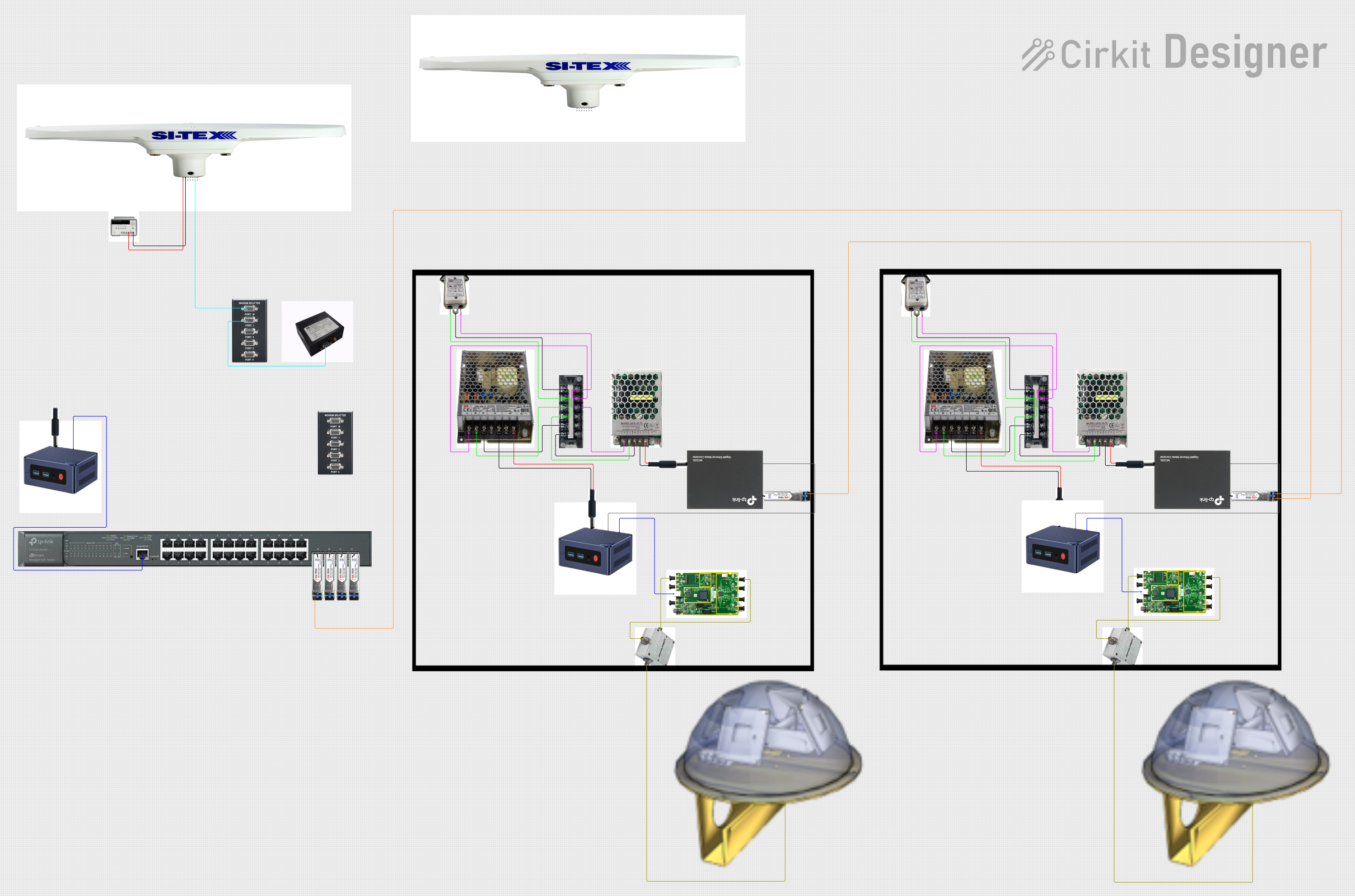
Satellite-Based Timing and Navigation System with SDR and Atomic Clock Synchronization
Image of GPS 시스템 측정 구성도_Confirm: A project utilizing Telescopic Antenna in a practical application
This circuit appears to be a complex system involving power supply management, GPS and timing synchronization, and data communication. It includes a SI-TEX G1 Satellite Compass for GPS data, an XHTF1021 Atomic Rubidium Clock for precise timing, and Ettus USRP B200 units for software-defined radio communication. Power is supplied through various SMPS units and distributed via terminal blocks and DC jacks. Data communication is facilitated by Beelink MINI S12 N95 computers, RS232 splitters, and a 1000BASE-T Media Converter for network connectivity. RF Directional Couplers are used to interface antennas with the USRP units, and the entire system is likely contained within cases for protection and organization.
Cirkit Designer LogoOpen Project in Cirkit Designer
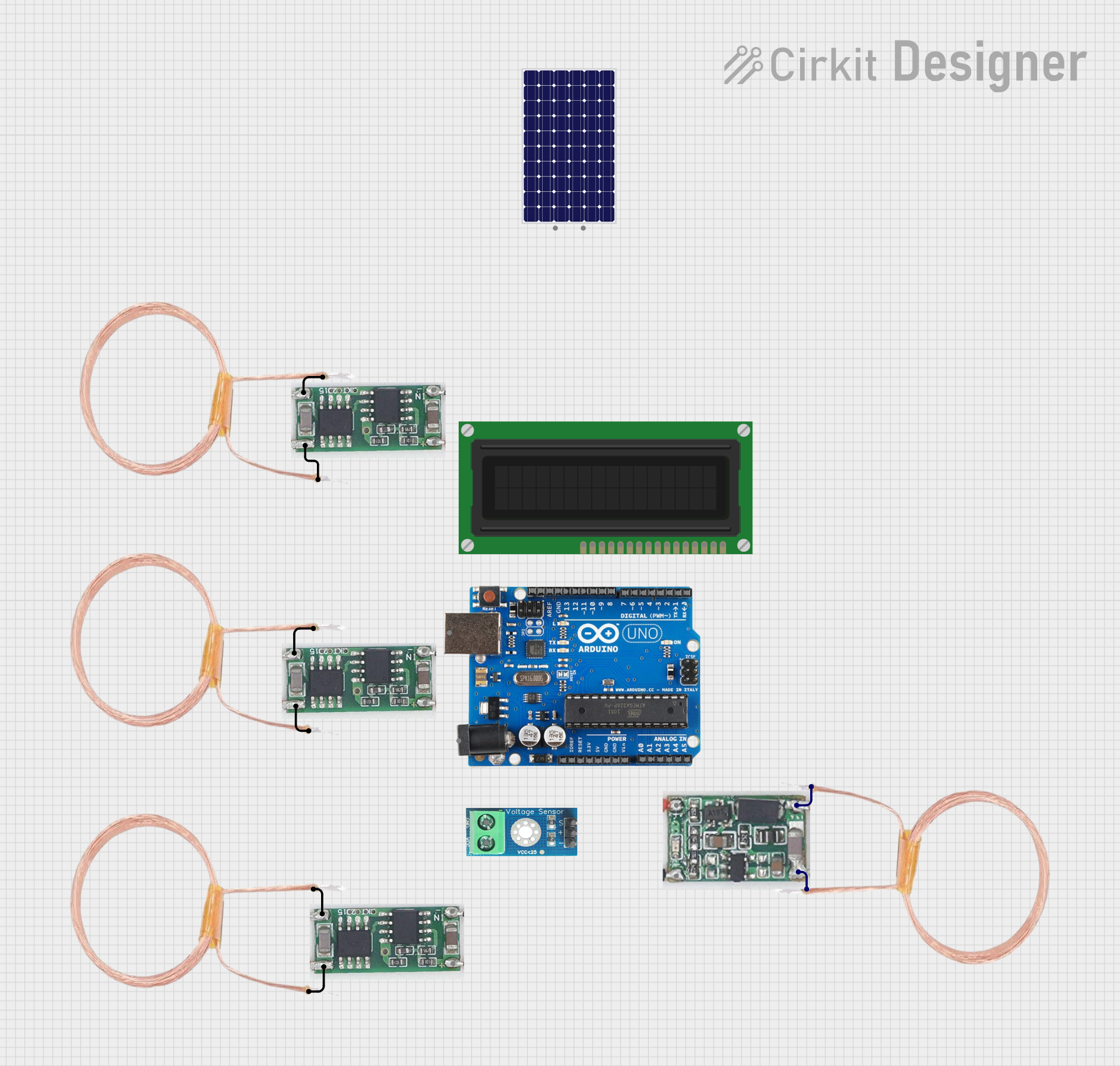
Arduino-Based Wireless Power Transmission System with Copper Coils
Image of nagesh: A project utilizing Telescopic Antenna in a practical application
This circuit consists of multiple copper coils connected to transmitters and a receiver, likely forming a wireless power transfer or communication system. The transmitters are connected to individual coils, and the receiver is connected to another coil, facilitating the transmission and reception of signals or power wirelessly.
Cirkit Designer LogoOpen Project in Cirkit Designer
Laptop-Connected Adalm Pluto SDR with Dual Antennas
Image of Zidan Project: A project utilizing Telescopic Antenna in a practical application
This circuit connects an Adalm Pluto Software Defined Radio (SDR) to a laptop via a Type-B to USB cable, allowing the laptop to control the SDR and process signals. Additionally, two antennas are connected to the Adalm Pluto SDR, which are likely used for transmitting and receiving radio signals as part of the SDR's functionality.
Cirkit Designer LogoOpen Project in Cirkit Designer

Explore Projects Built with Telescopic Antenna

Use Cirkit Designer to design, explore, and prototype these projects online. Some projects support real-time simulation. Click "Open Project" to start designing instantly!
Image of GPS 시스템 측정 구성도_241016: A project utilizing Telescopic Antenna in a practical application
Satellite Compass and Network-Integrated GPS Data Processing System
This circuit comprises a satellite compass, a mini PC, two GPS antennas, power supplies, a network switch, media converters, and an atomic rubidium clock. The satellite compass is powered by a triple output DC power supply and interfaces with an RS232 splitter for 1PPS signals. The mini PCs are connected to the USRP B200 devices via USB for data and power, and to media converters via Ethernet, which in turn connect to a network switch using fiber optic links. The antennas are connected to the USRP B200s through RF directional couplers, and the atomic clock provides a 1PPS input to the RS232 splitter.
Cirkit Designer LogoOpen Project in Cirkit Designer
Image of GPS 시스템 측정 구성도_Confirm: A project utilizing Telescopic Antenna in a practical application
Satellite-Based Timing and Navigation System with SDR and Atomic Clock Synchronization
This circuit appears to be a complex system involving power supply management, GPS and timing synchronization, and data communication. It includes a SI-TEX G1 Satellite Compass for GPS data, an XHTF1021 Atomic Rubidium Clock for precise timing, and Ettus USRP B200 units for software-defined radio communication. Power is supplied through various SMPS units and distributed via terminal blocks and DC jacks. Data communication is facilitated by Beelink MINI S12 N95 computers, RS232 splitters, and a 1000BASE-T Media Converter for network connectivity. RF Directional Couplers are used to interface antennas with the USRP units, and the entire system is likely contained within cases for protection and organization.
Cirkit Designer LogoOpen Project in Cirkit Designer
Image of nagesh: A project utilizing Telescopic Antenna in a practical application
Arduino-Based Wireless Power Transmission System with Copper Coils
This circuit consists of multiple copper coils connected to transmitters and a receiver, likely forming a wireless power transfer or communication system. The transmitters are connected to individual coils, and the receiver is connected to another coil, facilitating the transmission and reception of signals or power wirelessly.
Cirkit Designer LogoOpen Project in Cirkit Designer
Image of Zidan Project: A project utilizing Telescopic Antenna in a practical application
Laptop-Connected Adalm Pluto SDR with Dual Antennas
This circuit connects an Adalm Pluto Software Defined Radio (SDR) to a laptop via a Type-B to USB cable, allowing the laptop to control the SDR and process signals. Additionally, two antennas are connected to the Adalm Pluto SDR, which are likely used for transmitting and receiving radio signals as part of the SDR's functionality.
Cirkit Designer LogoOpen Project in Cirkit Designer

Technical Specifications

Key Technical Details

Parameter Value
Frequency Range 30 MHz to 1 GHz
Maximum Length 1.2 meters (47.2 inches)
Minimum Length 0.2 meters (7.9 inches)
Impedance 50 ohms
Connector Type BNC, SMA, or custom
Material Stainless steel or aluminum
Weight 50 grams (approx.)

Pin Configuration and Descriptions

Pin Number Description
1 Signal (connects to the receiver)
2 Ground (connects to the ground)

Usage Instructions

How to Use the Component in a Circuit

  1. Identify the Connector Type: Determine the type of connector your telescopic antenna uses (e.g., BNC, SMA).
  2. Connect to Receiver/Transmitter: Attach the antenna to the corresponding port on your receiver or transmitter device.
  3. Extend the Antenna: Pull the antenna to its full length to maximize signal reception or transmission.
  4. Adjust for Optimal Performance: Fine-tune the length and orientation of the antenna to achieve the best signal quality.

Important Considerations and Best Practices

  • Avoid Physical Damage: Handle the antenna with care to prevent bending or breaking.
  • Environmental Factors: Be aware of environmental factors such as obstacles and weather conditions that may affect signal quality.
  • Proper Grounding: Ensure the antenna is properly grounded to avoid interference and improve performance.
  • Regular Maintenance: Periodically clean the antenna to remove dust and debris that may affect its performance.

Troubleshooting and FAQs

Common Issues Users Might Face

  1. Poor Signal Reception:

    • Solution: Extend the antenna fully and adjust its orientation. Ensure there are no large obstacles blocking the signal path.
  2. Physical Damage:

    • Solution: Inspect the antenna for bends or breaks. Replace the antenna if it is damaged.
  3. Interference:

    • Solution: Ensure the antenna is properly grounded. Move the antenna away from other electronic devices that may cause interference.

FAQs

Q1: Can I use a telescopic antenna with my Arduino UNO?

  • A1: Yes, you can use a telescopic antenna with an Arduino UNO for wireless communication projects. You will need a compatible RF module (e.g., 433 MHz RF module) to interface with the antenna.

Q2: How do I clean my telescopic antenna?

  • A2: Use a soft cloth dampened with a mild cleaning solution to gently wipe the antenna. Avoid using abrasive materials that may scratch the surface.

Q3: What is the optimal length for my telescopic antenna?

  • A3: The optimal length depends on the frequency of the signal you are trying to receive or transmit. Generally, extending the antenna to its full length provides the best performance.

Example Code for Arduino UNO

Here is an example code to use a 433 MHz RF module with a telescopic antenna on an Arduino UNO:

#include <RH_ASK.h>
#include <SPI.h> // Not actually used but needed to compile

RH_ASK driver;

void setup() {
    Serial.begin(9600); // Initialize serial communication
    if (!driver.init()) {
        Serial.println("Initialization failed");
    }
}

void loop() {
    const char *msg = "Hello, world!";
    driver.send((uint8_t *)msg, strlen(msg));
    driver.waitPacketSent();
    delay(1000); // Wait for 1 second before sending the next message
}

Note: Ensure you have the RH_ASK library installed in your Arduino IDE. This code sends a simple "Hello, world!" message using a 433 MHz RF module connected to a telescopic antenna.

By following this documentation, users can effectively utilize a telescopic antenna in their projects, ensuring optimal performance and troubleshooting common issues.