
How to Use Power Inverter: Examples, Pinouts, and Specs
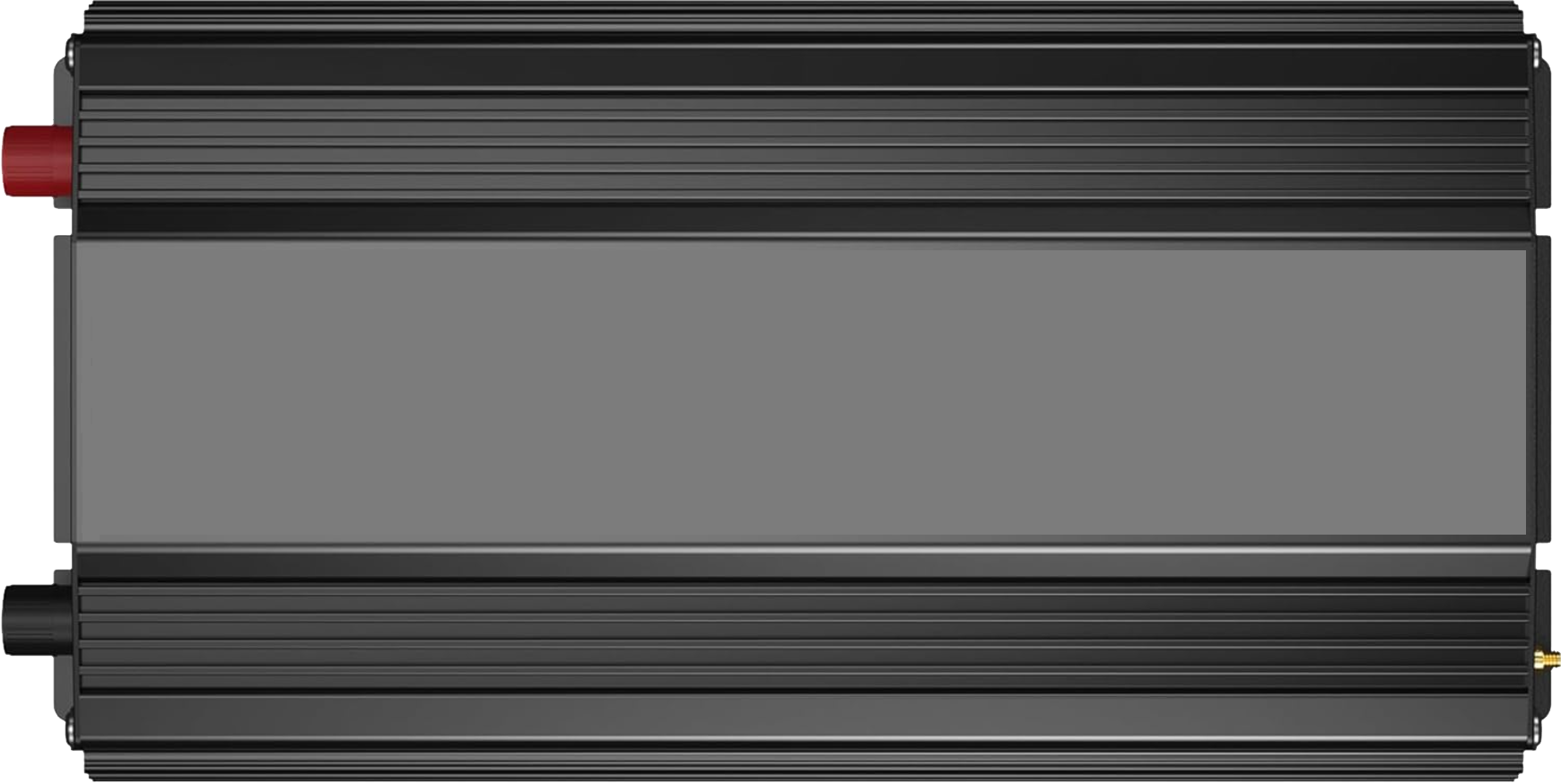
 Design with Power Inverter in Cirkit Designer
Introduction
The VOLTWORKS Store ETL UL458 12V DC to 220V AC 4000W Power Inverter is a high-performance electronic device designed to convert 12V DC power from sources such as batteries into 220V AC power. This enables the operation of AC-powered devices in environments where only DC power is available, such as vehicles, off-grid solar systems, or remote locations.
Explore Projects Built with Power Inverter
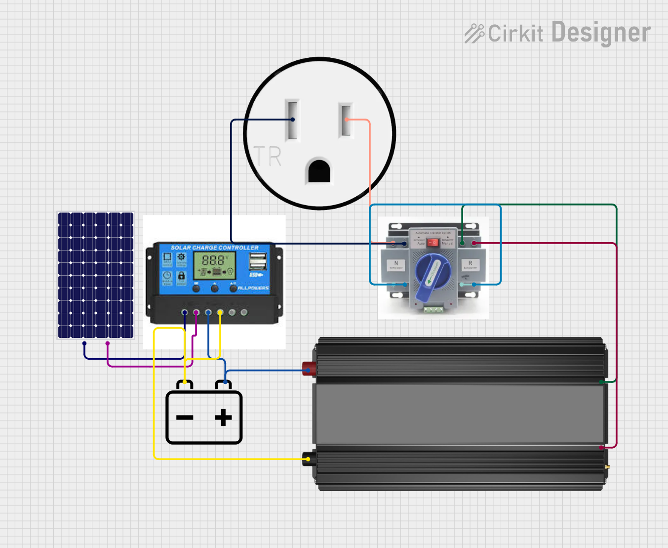 Open Project in Cirkit Designer
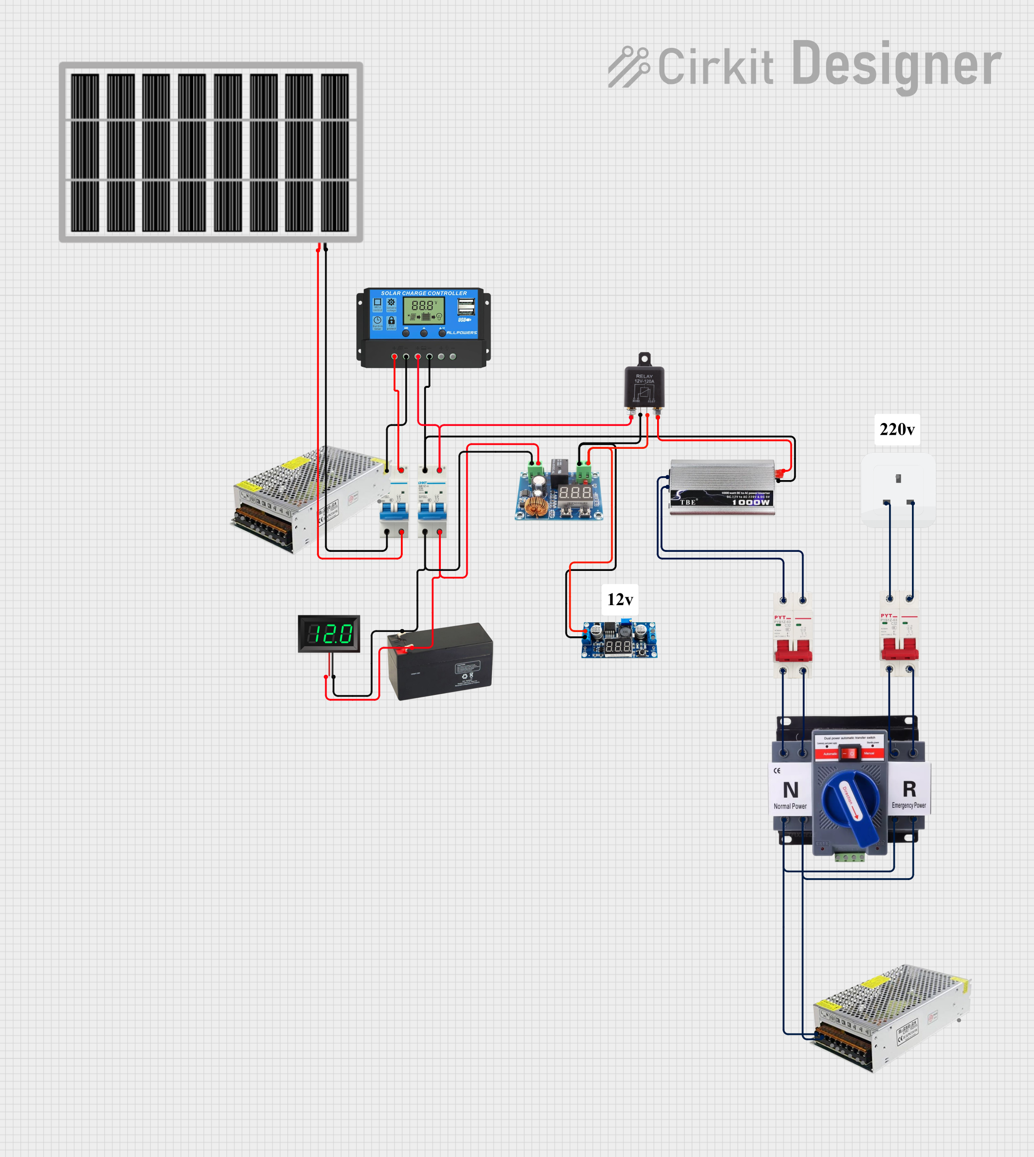 Open Project in Cirkit Designer
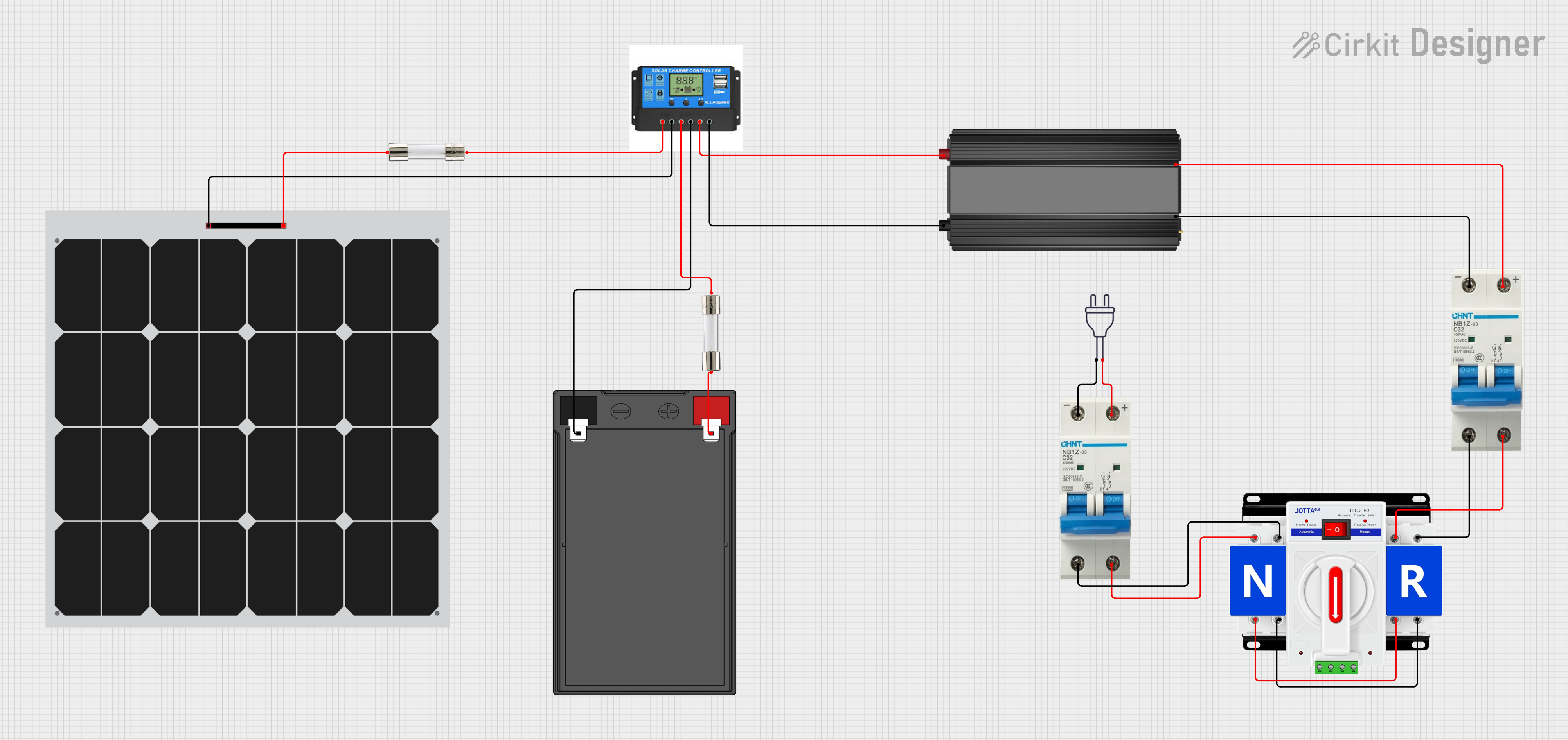 Open Project in Cirkit Designer
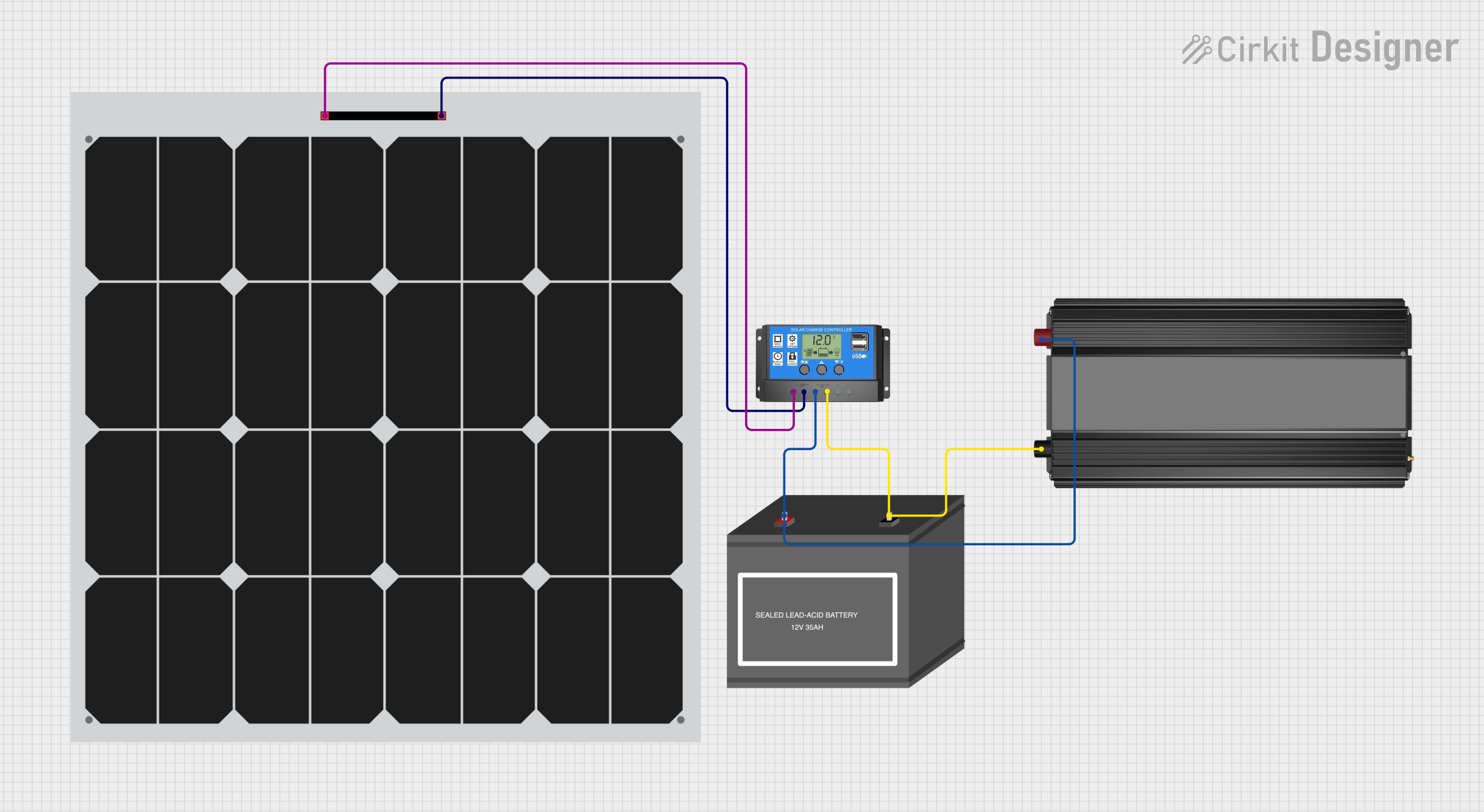 Open Project in Cirkit Designer
Explore Projects Built with Power Inverter
Open Project in Cirkit DesignerOpen Project in Cirkit DesignerOpen Project in Cirkit DesignerOpen Project in Cirkit DesignerCommon Applications and Use Cases
- Powering household appliances (e.g., refrigerators, microwaves, TVs) in off-grid setups.
- Providing AC power for tools and equipment in vehicles or remote job sites.
- Supporting emergency backup power systems during outages.
- Enabling portable power solutions for camping, RVs, and boats.
Technical Specifications
The following table outlines the key technical details of the ETL UL458 12V DC to 220V AC 4000W Power Inverter:
| Specification | Details |
|---|---|
| Input Voltage | 12V DC |
| Output Voltage | 220V AC ± 5% |
| Continuous Power | 4000W |
| Peak Power | 8000W |
| Output Waveform | Pure Sine Wave |
| Frequency | 50Hz ± 1% |
| Efficiency | Up to 90% |
| No-Load Current Draw | < 1.5A |
| Protection Features | Overload, over-temperature, short circuit, low voltage, and over-voltage |
| Cooling System | Intelligent temperature-controlled fan |
| Operating Temperature | -10°C to 40°C |
| Dimensions | 16.5 x 9.8 x 4.3 inches |
| Weight | 10.5 lbs (approx.) |
| Certifications | ETL UL458 compliant |
Pin Configuration and Descriptions
The power inverter has the following key input/output connections:
| Pin/Port | Description |
|---|---|
| DC Input Terminals | Connect to a 12V DC battery (positive and negative terminals). |
| AC Output Sockets | Standard 220V AC outlets for connecting appliances or devices. |
| USB Ports | USB output ports for charging small devices (e.g., phones, tablets). |
| Ground Terminal | Connect to the ground for safety and to reduce electrical noise. |
| Remote Control Port | Allows connection of an optional remote control for convenient operation. |
Usage Instructions
How to Use the Power Inverter in a Circuit
Connect the DC Input Terminals:
- Ensure the power source is a 12V DC battery with sufficient capacity to handle the inverter's power requirements.
- Use appropriately rated cables to connect the positive and negative terminals of the inverter to the battery.
- Double-check polarity to avoid damage.
Ground the Inverter:
- Connect the ground terminal of the inverter to a proper earth ground to ensure safety and reduce electrical noise.
Connect AC Devices:
- Plug your AC-powered devices into the inverter's AC output sockets.
- Ensure the total power consumption of connected devices does not exceed the inverter's continuous power rating (4000W).
Turn On the Inverter:
- Use the power switch or optional remote control to turn on the inverter.
- Verify that the inverter's status indicators (e.g., power, fault) are functioning correctly.
Monitor Operation:
- Keep an eye on the inverter's temperature and ensure proper ventilation.
- Avoid overloading the inverter or running it continuously at peak power.
Important Considerations and Best Practices
- Battery Capacity: Use a battery with sufficient capacity to support the inverter's power requirements. For example, a 4000W load at 12V DC will draw approximately 333A, so a high-capacity deep-cycle battery or battery bank is recommended.
- Cable Sizing: Use thick, low-resistance cables to minimize voltage drop and heat generation. Refer to the inverter's manual for recommended cable sizes.
- Ventilation: Ensure the inverter is installed in a well-ventilated area to prevent overheating.
- Load Management: Avoid connecting devices with a combined power draw exceeding the inverter's continuous power rating.
- Safety: Always disconnect the inverter from the battery when not in use to prevent accidental discharge.
Arduino UNO Integration
While power inverters are not directly controlled by Arduino boards, you can use an Arduino UNO to monitor the inverter's input/output parameters (e.g., voltage, current) using appropriate sensors. Below is an example code snippet for monitoring DC input voltage:
// Arduino code to monitor DC input voltage of the power inverter
const int voltagePin = A0; // Analog pin connected to voltage sensor
const float voltageDividerRatio = 11.0; // Adjust based on your voltage divider circuit
const float referenceVoltage = 5.0; // Arduino's reference voltage (5V for most boards)

void setup() {
  Serial.begin(9600); // Initialize serial communication
  pinMode(voltagePin, INPUT); // Set the voltage pin as input
}

void loop() {
  int sensorValue = analogRead(voltagePin); // Read the analog value
  float voltage = (sensorValue * referenceVoltage / 1023.0) * voltageDividerRatio;

  // Print the measured voltage to the Serial Monitor
  Serial.print("Input Voltage: ");
  Serial.print(voltage);
  Serial.println(" V");

  delay(1000); // Wait for 1 second before the next reading
}
Note: Use a voltage divider circuit to scale down the 12V input to a safe level for the Arduino's analog input pins.
Troubleshooting and FAQs
Common Issues and Solutions
| Issue | Possible Cause | Solution |
|---|---|---|
| Inverter does not turn on | Battery voltage is too low | Recharge or replace the battery. Ensure the voltage is within the 12V range. |
| Overload protection activates | Connected devices exceed power rating | Disconnect some devices to reduce the load. |
| Inverter shuts down due to overheating | Poor ventilation or high ambient temperature | Improve airflow around the inverter and ensure proper ventilation. |
| AC devices do not work properly | Incompatible device or waveform requirements | Ensure the device is compatible with a pure sine wave inverter. |
| High no-load current draw | Faulty internal components | Contact the manufacturer for support or repair. |
FAQs
Can I use this inverter with a 24V battery?
- No, this inverter is designed specifically for 12V DC input. Using a 24V battery may damage the inverter.
What is the difference between continuous and peak power?
- Continuous power (4000W) is the maximum power the inverter can supply indefinitely. Peak power (8000W) is the short-term power the inverter can handle for surges, such as when starting motors.
Can I connect solar panels directly to the inverter?
- No, solar panels should be connected to a charge controller, which then charges the battery. The inverter should be connected to the battery.
How do I know if the inverter is overloaded?
- The inverter will typically shut down and display a fault indicator if overloaded. Reduce the load and restart the inverter.
By following this documentation, users can safely and effectively utilize the VOLTWORKS Store ETL UL458 12V DC to 220V AC 4000W Power Inverter for a variety of applications.