Cirkit Designer Logo
Cirkit Designer
Your all-in-one circuit design IDE
Home / 
Component Documentation

How to Use UPS battery: Examples, Pinouts, and Specs

Image of UPS battery
Cirkit Designer LogoDesign with UPS battery in Cirkit Designer

Introduction

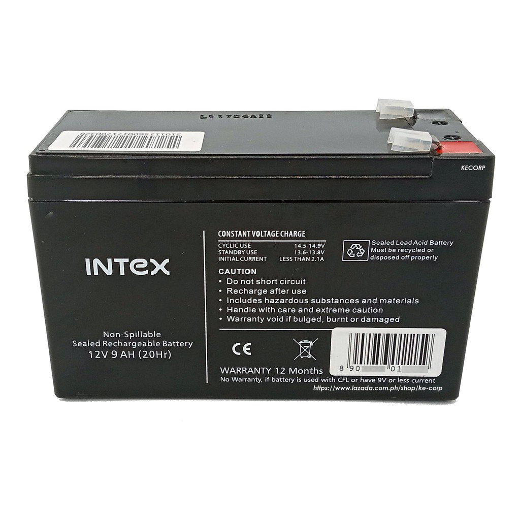
A UPS (Uninterruptible Power Supply) battery is a critical component in power backup systems. It is designed to provide emergency power to a load, such as a computer, medical equipment, or telecommunications device, when the primary power source, typically the mains electricity, fails. UPS batteries ensure continuity of operation and prevent data loss or damage to electrical equipment during power outages.

Explore Projects Built with UPS battery

Use Cirkit Designer to design, explore, and prototype these projects online. Some projects support real-time simulation. Click "Open Project" to start designing instantly!
12V UPS System with Dual 18650 Li-ion Battery Backup and Voltage Regulation
Image of Power supply: A project utilizing UPS battery in a practical application
This circuit is designed to provide an uninterruptible power supply (UPS) system with a 12V DC output. It includes a 12V 5A power supply connected to an AC source through a toggle switch, which charges a pair of 18650 Li-ion batteries via a voltage regulator (XL4016). The UPS module ensures a continuous power supply to the load by switching between the power supply and the battery bank.
Cirkit Designer LogoOpen Project in Cirkit Designer
Battery-Powered UPS with Step-Down Buck Converter and BMS
Image of Mini ups: A project utilizing UPS battery in a practical application
This circuit is a power management system that steps down a 240V AC input to a lower DC voltage using a buck converter, which then powers a 40W UPS. The UPS is controlled by a rocker switch and is backed up by a battery management system (BMS) connected to three 3.7V batteries in series, ensuring continuous power supply.
Cirkit Designer LogoOpen Project in Cirkit Designer
ESP32-S3 Battery-Powered Environmental Monitoring System with OLED Display
Image of Diagram wiring: A project utilizing UPS battery in a practical application
This circuit is a sensor and display system powered by a UPS module with a 12V power supply and 18650 batteries. It includes an ESP32 microcontroller that interfaces with various sensors (DHT22, Strain Gauge, MPU-6050, ADXL345) and an OLED display, with power regulation provided by a step-down buck converter.
Cirkit Designer LogoOpen Project in Cirkit Designer
Solar-Powered UPS with Multiple Battery Management
Image of schematic: A project utilizing UPS battery in a practical application
This circuit is designed to integrate a solar power system with multiple 12V batteries and a UPS module for uninterrupted power supply. The solar panel charges the batteries through a charge controller, which is protected by DC MCBs. The UPS modules are connected to the batteries and provide a regulated DC output, which is then adjusted by an XL4016 DC-DC converter module.
Cirkit Designer LogoOpen Project in Cirkit Designer

Explore Projects Built with UPS battery

Use Cirkit Designer to design, explore, and prototype these projects online. Some projects support real-time simulation. Click "Open Project" to start designing instantly!
Image of Power supply: A project utilizing UPS battery in a practical application
12V UPS System with Dual 18650 Li-ion Battery Backup and Voltage Regulation
This circuit is designed to provide an uninterruptible power supply (UPS) system with a 12V DC output. It includes a 12V 5A power supply connected to an AC source through a toggle switch, which charges a pair of 18650 Li-ion batteries via a voltage regulator (XL4016). The UPS module ensures a continuous power supply to the load by switching between the power supply and the battery bank.
Cirkit Designer LogoOpen Project in Cirkit Designer
Image of Mini ups: A project utilizing UPS battery in a practical application
Battery-Powered UPS with Step-Down Buck Converter and BMS
This circuit is a power management system that steps down a 240V AC input to a lower DC voltage using a buck converter, which then powers a 40W UPS. The UPS is controlled by a rocker switch and is backed up by a battery management system (BMS) connected to three 3.7V batteries in series, ensuring continuous power supply.
Cirkit Designer LogoOpen Project in Cirkit Designer
Image of Diagram wiring: A project utilizing UPS battery in a practical application
ESP32-S3 Battery-Powered Environmental Monitoring System with OLED Display
This circuit is a sensor and display system powered by a UPS module with a 12V power supply and 18650 batteries. It includes an ESP32 microcontroller that interfaces with various sensors (DHT22, Strain Gauge, MPU-6050, ADXL345) and an OLED display, with power regulation provided by a step-down buck converter.
Cirkit Designer LogoOpen Project in Cirkit Designer
Image of schematic: A project utilizing UPS battery in a practical application
Solar-Powered UPS with Multiple Battery Management
This circuit is designed to integrate a solar power system with multiple 12V batteries and a UPS module for uninterrupted power supply. The solar panel charges the batteries through a charge controller, which is protected by DC MCBs. The UPS modules are connected to the batteries and provide a regulated DC output, which is then adjusted by an XL4016 DC-DC converter module.
Cirkit Designer LogoOpen Project in Cirkit Designer

Common Applications and Use Cases

  • Computer systems and data centers
  • Medical and laboratory equipment
  • Telecommunication systems
  • Industrial control systems
  • Security systems

Technical Specifications

Key Technical Details

Specification Description
Voltage Typically 12V or 24V (varies by model)
Capacity Ranges from a few Ah (Ampere-hours) to several hundred Ah
Chemistry Commonly Lead-Acid, Li-ion, or NiMH
Cycle Life Depends on battery type and depth of discharge
Operating Temperature Varies by model, often 0°C to 40°C

Pin Configuration and Descriptions

UPS batteries typically come with two terminals:

Terminal Description
Positive (+) The terminal to connect to the positive side of the load or charging circuit
Negative (-) The terminal to connect to the negative side of the load or charging circuit

Usage Instructions

How to Use the UPS Battery in a Circuit

  1. Installation: Ensure the UPS battery is installed in a compatible UPS system according to the manufacturer's instructions.
  2. Connection: Connect the positive terminal of the battery to the positive input of the UPS and the negative terminal to the negative input.
  3. Charging: Allow the UPS to charge the battery fully before use. This may take several hours.
  4. Operation: The UPS will automatically switch to battery power when it detects a loss of mains electricity.

Important Considerations and Best Practices

  • Ventilation: Lead-acid batteries can produce hydrogen gas; ensure proper ventilation.
  • Temperature: Avoid exposing the battery to extreme temperatures to prevent capacity loss.
  • Maintenance: Regularly check the battery's state of charge and health.
  • Recycling: Dispose of UPS batteries properly, as they contain hazardous materials.

Troubleshooting and FAQs

Common Issues

  • Battery not charging: Check connections, ensure the UPS is plugged in, and the battery is not at the end of its life.
  • Reduced runtime: The battery may be aging or damaged. Test the battery's capacity and replace if necessary.
  • Swollen battery case: Indicates overcharging or failure. Replace the battery and check the UPS charging system.

Solutions and Tips for Troubleshooting

  • Battery Replacement: Use only compatible batteries recommended by the UPS manufacturer.
  • Regular Testing: Perform regular tests to ensure the UPS switches to battery power correctly.
  • Professional Help: For complex issues, consult with a professional or the manufacturer's support.

FAQs

Q: How long does a UPS battery last? A: The lifespan of a UPS battery varies but typically ranges from 3 to 5 years.

Q: Can I replace the UPS battery myself? A: Yes, if you follow the manufacturer's guidelines and take appropriate safety precautions.

Q: How do I know when to replace my UPS battery? A: Replace the battery if it fails to hold a charge, provides reduced runtime, or shows physical signs of damage.

Q: Is it safe to keep a UPS battery plugged in all the time? A: Yes, UPS systems are designed to be plugged in continuously and will manage the charging process to maintain the battery.

Example Code for Arduino UNO Connection

// This example assumes the use of a UPS battery to power an Arduino UNO
// during a power outage. The Arduino monitors the mains power status and
// switches to UPS battery power if mains power is lost.

int mainsPowerPin = 2; // Connect to a sensor that detects mains power status
int batteryPowerPin = 3; // Connect to a sensor that detects battery power status

void setup() {
  pinMode(mainsPowerPin, INPUT);
  pinMode(batteryPowerPin, INPUT);
  Serial.begin(9600);
}

void loop() {
  bool mainsPower = digitalRead(mainsPowerPin);
  bool batteryPower = digitalRead(batteryPowerPin);

  if (!mainsPower && batteryPower) {
    // Mains power is out, and the battery is providing power
    Serial.println("Switched to UPS battery power.");
  } else if (mainsPower) {
    // Mains power is available
    Serial.println("Running on mains power.");
  } else {
    // Neither mains power nor battery power is available
    Serial.println("No power available.");
  }

  delay(1000); // Wait for 1 second before checking again
}

Note: The above code is a conceptual example. In practice, a UPS system would handle the power switching automatically, and the Arduino would not need to monitor power sources unless it's part of a larger system that requires such functionality.