Cirkit Designer Logo
Cirkit Designer
Your all-in-one circuit design IDE
Home / 
Component Documentation

How to Use GY_511: Examples, Pinouts, and Specs

Image of GY_511
Cirkit Designer LogoDesign with GY_511 in Cirkit Designer

Introduction

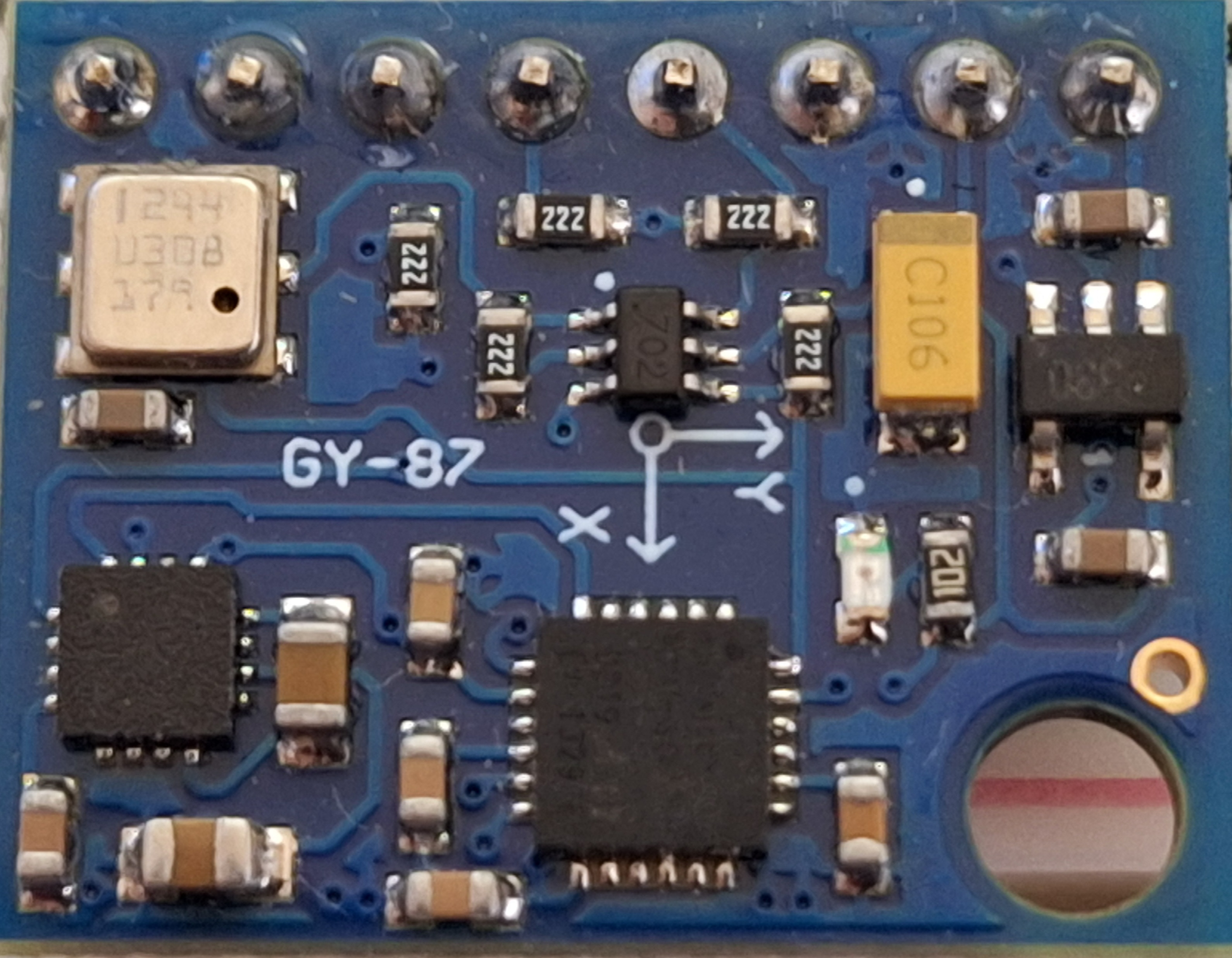
The GY-511 is a digital compass module based on the HMC5883L sensor, designed to provide precise heading and orientation information. It measures the Earth's magnetic field in three axes (X, Y, and Z) and outputs the data digitally via the I2C communication protocol. This module is widely used in robotics, navigation systems, drones, and other applications requiring accurate directional data.

Explore Projects Built with GY_511

Use Cirkit Designer to design, explore, and prototype these projects online. Some projects support real-time simulation. Click "Open Project" to start designing instantly!
Arduino 101 Based RFID and GSM Security System with I2C LCD Display and RTC
Image of id scanner with messaging system: A project utilizing GY_511 in a practical application
This circuit features an Arduino 101 microcontroller interfaced with an RFID-RC522 module for RFID reading, a GSM SIM900 module for cellular communication, a DS3231 Real Time Clock for timekeeping, and an I2C LCD screen for display. The Arduino controls a buzzer connected to its D7 pin and communicates with the GSM module via serial connection on pins D0/RX and D1/TX. The RFID, RTC, and LCD modules are powered by the Arduino's 5V and 3.3V outputs, and they use I2C (SCL/SDA) for communication, except for the RFID module which uses SPI (MISO/MOSI/SCK) and a digital pin for reset (D9).
Cirkit Designer LogoOpen Project in Cirkit Designer
Arduino UNO R4 WiFi Controlled Potentiometer Level Display
Image of インジケータボリューム変調LED: A project utilizing GY_511 in a practical application
This circuit features an Arduino UNO R4 WiFi microcontroller connected to a TM1651 display module (referred to as 'YY') and a potentiometer. The Arduino controls the display via digital pins D2 and D3, which are connected to the DIO and CLK pins of the TM1651, respectively. The potentiometer's output is read by the Arduino's analog pin A0 and is used to adjust the display level on the TM1651, indicating a value that likely represents a battery level or similar variable input.
Cirkit Designer LogoOpen Project in Cirkit Designer
Arduino Mega 2560 Based Security System with Fingerprint Authentication and SMS Alerts
Image of Door security system: A project utilizing GY_511 in a practical application
This circuit features an Arduino Mega 2560 microcontroller interfaced with a SIM800L GSM module, two fingerprint scanners, an I2C LCD display, an IR sensor, and a piezo buzzer. Power management is handled by a PowerBoost 1000 Basic Pad USB, a TP4056 charging module, and a Li-ion 18650 battery, with an option to use a Mini AC-DC 110V-230V to 5V 700mA module for direct power supply. The primary functionality appears to be a security system with GSM communication capabilities, biometric access control, and visual/audible feedback.
Cirkit Designer LogoOpen Project in Cirkit Designer
Arduino-Based Water Quality Monitoring System with SIM900A and Multiple Sensors
Image of feito: A project utilizing GY_511 in a practical application
This circuit is a water quality monitoring system that uses an Arduino UNO to collect data from a YF-S201 water flow meter, a turbidity sensor, and a temperature sensor. The collected data is then transmitted via a SIM900A GSM module to a remote server or user through SMS. The system measures water flow rate, temperature, and turbidity, and sends periodic updates.
Cirkit Designer LogoOpen Project in Cirkit Designer

Explore Projects Built with GY_511

Use Cirkit Designer to design, explore, and prototype these projects online. Some projects support real-time simulation. Click "Open Project" to start designing instantly!
Image of id scanner with messaging system: A project utilizing GY_511 in a practical application
Arduino 101 Based RFID and GSM Security System with I2C LCD Display and RTC
This circuit features an Arduino 101 microcontroller interfaced with an RFID-RC522 module for RFID reading, a GSM SIM900 module for cellular communication, a DS3231 Real Time Clock for timekeeping, and an I2C LCD screen for display. The Arduino controls a buzzer connected to its D7 pin and communicates with the GSM module via serial connection on pins D0/RX and D1/TX. The RFID, RTC, and LCD modules are powered by the Arduino's 5V and 3.3V outputs, and they use I2C (SCL/SDA) for communication, except for the RFID module which uses SPI (MISO/MOSI/SCK) and a digital pin for reset (D9).
Cirkit Designer LogoOpen Project in Cirkit Designer
Image of インジケータボリューム変調LED: A project utilizing GY_511 in a practical application
Arduino UNO R4 WiFi Controlled Potentiometer Level Display
This circuit features an Arduino UNO R4 WiFi microcontroller connected to a TM1651 display module (referred to as 'YY') and a potentiometer. The Arduino controls the display via digital pins D2 and D3, which are connected to the DIO and CLK pins of the TM1651, respectively. The potentiometer's output is read by the Arduino's analog pin A0 and is used to adjust the display level on the TM1651, indicating a value that likely represents a battery level or similar variable input.
Cirkit Designer LogoOpen Project in Cirkit Designer
Image of Door security system: A project utilizing GY_511 in a practical application
Arduino Mega 2560 Based Security System with Fingerprint Authentication and SMS Alerts
This circuit features an Arduino Mega 2560 microcontroller interfaced with a SIM800L GSM module, two fingerprint scanners, an I2C LCD display, an IR sensor, and a piezo buzzer. Power management is handled by a PowerBoost 1000 Basic Pad USB, a TP4056 charging module, and a Li-ion 18650 battery, with an option to use a Mini AC-DC 110V-230V to 5V 700mA module for direct power supply. The primary functionality appears to be a security system with GSM communication capabilities, biometric access control, and visual/audible feedback.
Cirkit Designer LogoOpen Project in Cirkit Designer
Image of feito: A project utilizing GY_511 in a practical application
Arduino-Based Water Quality Monitoring System with SIM900A and Multiple Sensors
This circuit is a water quality monitoring system that uses an Arduino UNO to collect data from a YF-S201 water flow meter, a turbidity sensor, and a temperature sensor. The collected data is then transmitted via a SIM900A GSM module to a remote server or user through SMS. The system measures water flow rate, temperature, and turbidity, and sends periodic updates.
Cirkit Designer LogoOpen Project in Cirkit Designer

Common Applications

  • Robotics for navigation and pathfinding
  • Drones and UAVs for orientation control
  • Handheld compasses and navigation devices
  • Augmented reality systems
  • Vehicle tracking and positioning systems

Technical Specifications

Below are the key technical details of the GY-511 module:

Parameter Value
Sensor Model HMC5883L
Manufacturer Part ID MP085
Communication Protocol I2C
Operating Voltage 3.3V to 5V
Operating Current 100 µA (typical)
Measurement Range ±1.3 to ±8 Gauss
Resolution 0.73 mG/LSB (at ±1.3 Gauss range)
Dimensions 14mm x 13mm x 3.5mm
Operating Temperature -40°C to +85°C

Pin Configuration

The GY-511 module has 4 pins for interfacing. The table below describes each pin:

Pin Name Description
1 VCC Power supply input (3.3V to 5V). Connect to the power source.
2 GND Ground. Connect to the ground of the circuit.
3 SDA I2C data line. Connect to the SDA pin of the microcontroller.
4 SCL I2C clock line. Connect to the SCL pin of the microcontroller.

Usage Instructions

How to Use the GY-511 in a Circuit

  1. Power the Module: Connect the VCC pin to a 3.3V or 5V power source and the GND pin to the ground.
  2. I2C Communication: Connect the SDA and SCL pins to the corresponding I2C pins on your microcontroller (e.g., Arduino UNO).
  3. Pull-Up Resistors: Ensure that the I2C lines (SDA and SCL) have pull-up resistors (typically 4.7kΩ). Some GY-511 modules include these resistors onboard.
  4. Addressing: The default I2C address of the HMC5883L sensor is 0x1E. Ensure no other devices on the I2C bus conflict with this address.
  5. Software Setup: Use a library or write custom code to initialize the sensor and read data.

Example Arduino Code

Below is an example of how to interface the GY-511 with an Arduino UNO using the Wire library:

#include <Wire.h>

// HMC5883L I2C address
#define HMC5883L_ADDRESS 0x1E

void setup() {
  Wire.begin(); // Initialize I2C communication
  Serial.begin(9600); // Start serial communication for debugging

  // Initialize the HMC5883L sensor
  Wire.beginTransmission(HMC5883L_ADDRESS);
  Wire.write(0x00); // Select configuration register A
  Wire.write(0x70); // Set 8-average, 15 Hz default, normal measurement
  Wire.endTransmission();

  Wire.beginTransmission(HMC5883L_ADDRESS);
  Wire.write(0x01); // Select configuration register B
  Wire.write(0xA0); // Set gain = 5
  Wire.endTransmission();

  Wire.beginTransmission(HMC5883L_ADDRESS);
  Wire.write(0x02); // Select mode register
  Wire.write(0x00); // Continuous measurement mode
  Wire.endTransmission();
}

void loop() {
  int16_t x, y, z;

  // Request 6 bytes of data from the sensor
  Wire.beginTransmission(HMC5883L_ADDRESS);
  Wire.write(0x03); // Start reading from data output X MSB register
  Wire.endTransmission();
  Wire.requestFrom(HMC5883L_ADDRESS, 6);

  if (Wire.available() == 6) {
    x = (Wire.read() << 8) | Wire.read(); // Combine MSB and LSB for X-axis
    z = (Wire.read() << 8) | Wire.read(); // Combine MSB and LSB for Z-axis
    y = (Wire.read() << 8) | Wire.read(); // Combine MSB and LSB for Y-axis
  }

  // Print the raw magnetometer data
  Serial.print("X: ");
  Serial.print(x);
  Serial.print(" Y: ");
  Serial.print(y);
  Serial.print(" Z: ");
  Serial.println(z);

  delay(500); // Wait for 500ms before the next reading
}

Important Considerations

  • Magnetic Interference: Avoid placing the GY-511 near ferromagnetic materials or strong magnetic fields, as they can distort readings.
  • Calibration: Perform a calibration routine to account for hard and soft iron distortions in your environment.
  • Orientation: Mount the module flat and ensure consistent orientation for accurate readings.

Troubleshooting and FAQs

Common Issues and Solutions

  1. No Data Output

    • Cause: Incorrect wiring or I2C address mismatch.
    • Solution: Double-check the connections and ensure the I2C address is set to 0x1E.
  2. Inaccurate Readings

    • Cause: Magnetic interference or lack of calibration.
    • Solution: Move the module away from magnetic sources and perform a calibration routine.
  3. I2C Communication Errors

    • Cause: Missing pull-up resistors or incorrect I2C clock speed.
    • Solution: Add 4.7kΩ pull-up resistors to SDA and SCL lines if not already present. Ensure the I2C clock speed is set to 100kHz.

FAQs

Q: Can the GY-511 operate at 5V?
A: Yes, the GY-511 module supports both 3.3V and 5V power supplies.

Q: How do I calibrate the GY-511?
A: Rotate the module in all directions while collecting data. Use the readings to calculate offsets and scaling factors to correct for distortions.

Q: What is the maximum range of the GY-511?
A: The HMC5883L sensor on the GY-511 can measure magnetic fields up to ±8 Gauss.

Q: Can I use the GY-511 with microcontrollers other than Arduino?
A: Yes, the GY-511 can be used with any microcontroller that supports I2C communication, such as Raspberry Pi, ESP32, or STM32.