How to Use TS3A5018 analog switch: Examples, Pinouts, and Specs
Introduction
The TS3A5018 is a low-voltage, dual-channel analog switch designed for routing analog signals in a variety of applications. It features low on-resistance (RON) and low power consumption, making it an ideal choice for battery-operated devices. The switch is controlled by a digital signal, allowing seamless integration into digital circuits. Its compact design and high performance make it suitable for applications such as audio signal routing, data acquisition systems, and portable electronics.
Explore Projects Built with TS3A5018 analog switch


Explore Projects Built with TS3A5018 analog switch
Common Applications
- Audio signal switching and routing
- Portable and battery-powered devices
- Data acquisition systems
- Test and measurement equipment
- Multiplexing analog signals in embedded systems
Technical Specifications
The TS3A5018 is a versatile component with the following key specifications:
| Parameter | Value |
|---|---|
| Supply Voltage (VDD) | 1.65V to 3.6V |
| On-Resistance (RON) | 0.8Ω (typical) at VDD = 3.0V |
| On-Resistance Flatness | 0.1Ω (typical) |
| Signal Range | 0V to VDD |
| Control Input Voltage | 0V to VDD |
| Bandwidth | 300 MHz |
| Quiescent Current (IQ) | 1 µA (typical) |
| Operating Temperature Range | -40°C to +85°C |
| Package Options | TSSOP-10, QFN-10 |
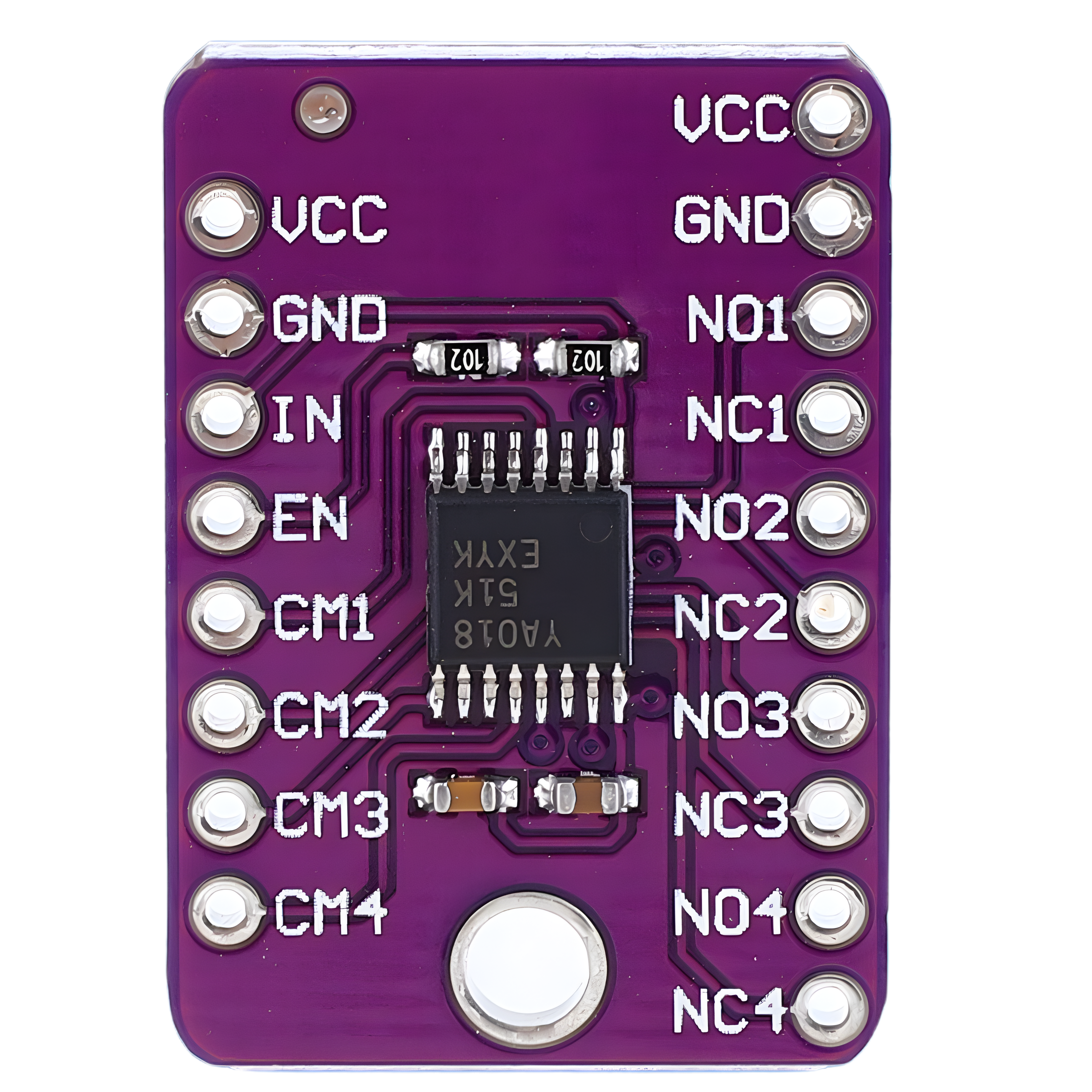
Pin Configuration and Descriptions
The TS3A5018 is available in a 10-pin package. Below is the pinout and description:
| Pin Number | Pin Name | Description |
|---|---|---|
| 1 | IN1 | Control input for switch 1 |
| 2 | COM1 | Common terminal for switch 1 |
| 3 | NO1 | Normally open terminal for switch 1 |
| 4 | GND | Ground |
| 5 | VDD | Positive supply voltage |
| 6 | NO2 | Normally open terminal for switch 2 |
| 7 | COM2 | Common terminal for switch 2 |
| 8 | IN2 | Control input for switch 2 |
| 9 | NC | No connection |
| 10 | NC | No connection |
Usage Instructions
How to Use the TS3A5018 in a Circuit
- Power Supply: Connect the VDD pin to a supply voltage between 1.65V and 3.6V. Connect the GND pin to the ground of the circuit.
- Control Signals: Apply a digital control signal (0V or VDD) to the IN1 and IN2 pins to control the state of the switches:
- Logic HIGH (VDD): The corresponding switch is closed, connecting COMx to NOx.
- Logic LOW (0V): The corresponding switch is open, isolating COMx from NOx.
- Signal Routing: Connect the analog signals to the COMx and NOx pins. Ensure the signal voltage stays within the range of 0V to VDD.
- Bypass Capacitors: Place a 0.1 µF decoupling capacitor close to the VDD pin to reduce noise and improve stability.
Important Considerations
- Signal Voltage Range: Ensure the input signal voltage does not exceed the supply voltage (VDD) to avoid damage.
- Load Impedance: Use a high-impedance load to minimize signal distortion caused by the switch's on-resistance.
- PCB Layout: Keep traces short and minimize parasitic capacitance to maintain signal integrity, especially for high-frequency signals.
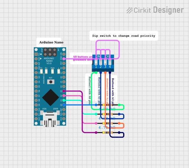
Example: Using TS3A5018 with Arduino UNO
The TS3A5018 can be controlled by an Arduino UNO to switch analog signals. Below is an example circuit and code:
Circuit Connections
- Connect VDD to the Arduino's 3.3V pin and GND to the Arduino's GND.
- Connect IN1 and IN2 to digital pins 7 and 8 of the Arduino, respectively.
- Connect the analog signal to COM1 and NO1 for the first switch.
Arduino Code
// Example code to control TS3A5018 analog switch with Arduino UNO

#define SWITCH1_CONTROL 7  // Pin connected to IN1
#define SWITCH2_CONTROL 8  // Pin connected to IN2

void setup() {
  pinMode(SWITCH1_CONTROL, OUTPUT); // Set pin 7 as output
  pinMode(SWITCH2_CONTROL, OUTPUT); // Set pin 8 as output

  // Initialize both switches to OFF state
  digitalWrite(SWITCH1_CONTROL, LOW);
  digitalWrite(SWITCH2_CONTROL, LOW);
}

void loop() {
  // Turn ON switch 1
  digitalWrite(SWITCH1_CONTROL, HIGH);
  delay(1000); // Keep switch 1 ON for 1 second

  // Turn OFF switch 1 and turn ON switch 2
  digitalWrite(SWITCH1_CONTROL, LOW);
  digitalWrite(SWITCH2_CONTROL, HIGH);
  delay(1000); // Keep switch 2 ON for 1 second

  // Turn OFF both switches
  digitalWrite(SWITCH2_CONTROL, LOW);
  delay(1000); // Wait for 1 second before repeating
}
Troubleshooting and FAQs
Common Issues and Solutions
Switch Not Responding to Control Signal
- Cause: Incorrect voltage levels on INx pins.
- Solution: Ensure the control signal is either 0V (LOW) or VDD (HIGH).
Signal Distortion
- Cause: High load current or long PCB traces.
- Solution: Use a high-impedance load and minimize trace lengths.
Excessive Power Consumption
- Cause: Floating control pins.
- Solution: Pull unused control pins to GND or VDD using a resistor.
Signal Voltage Exceeds VDD
- Cause: Input signal is outside the allowable range.
- Solution: Ensure the signal voltage is within 0V to VDD.
FAQs
Q1: Can the TS3A5018 handle digital signals?
A1: Yes, the TS3A5018 can route digital signals as long as the voltage levels are within the 0V to VDD range.
Q2: What is the maximum frequency the TS3A5018 can handle?
A2: The TS3A5018 has a bandwidth of 300 MHz, making it suitable for high-frequency signals.
Q3: Can I use the TS3A5018 with a 5V supply?
A3: No, the maximum supply voltage for the TS3A5018 is 3.6V. Using a 5V supply may damage the component.
Q4: How do I reduce noise in my circuit?
A4: Use a 0.1 µF decoupling capacitor near the VDD pin and keep traces short to minimize noise.