How to Use Maker Driver: Examples, Pinouts, and Specs
Introduction
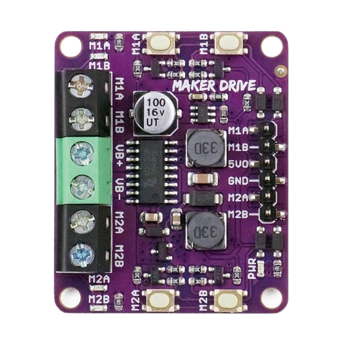
The Maker Driver (MAKER-DRIVE), manufactured by Cytron, is a compact and efficient motor driver designed for controlling DC motors in DIY electronics projects and robotics. It provides an easy-to-use interface for hobbyists and professionals to control motor speed and direction with minimal effort. The Maker Driver is particularly well-suited for low-power motor applications and is compatible with microcontrollers like Arduino, Raspberry Pi, and other development boards.
Explore Projects Built with Maker Driver
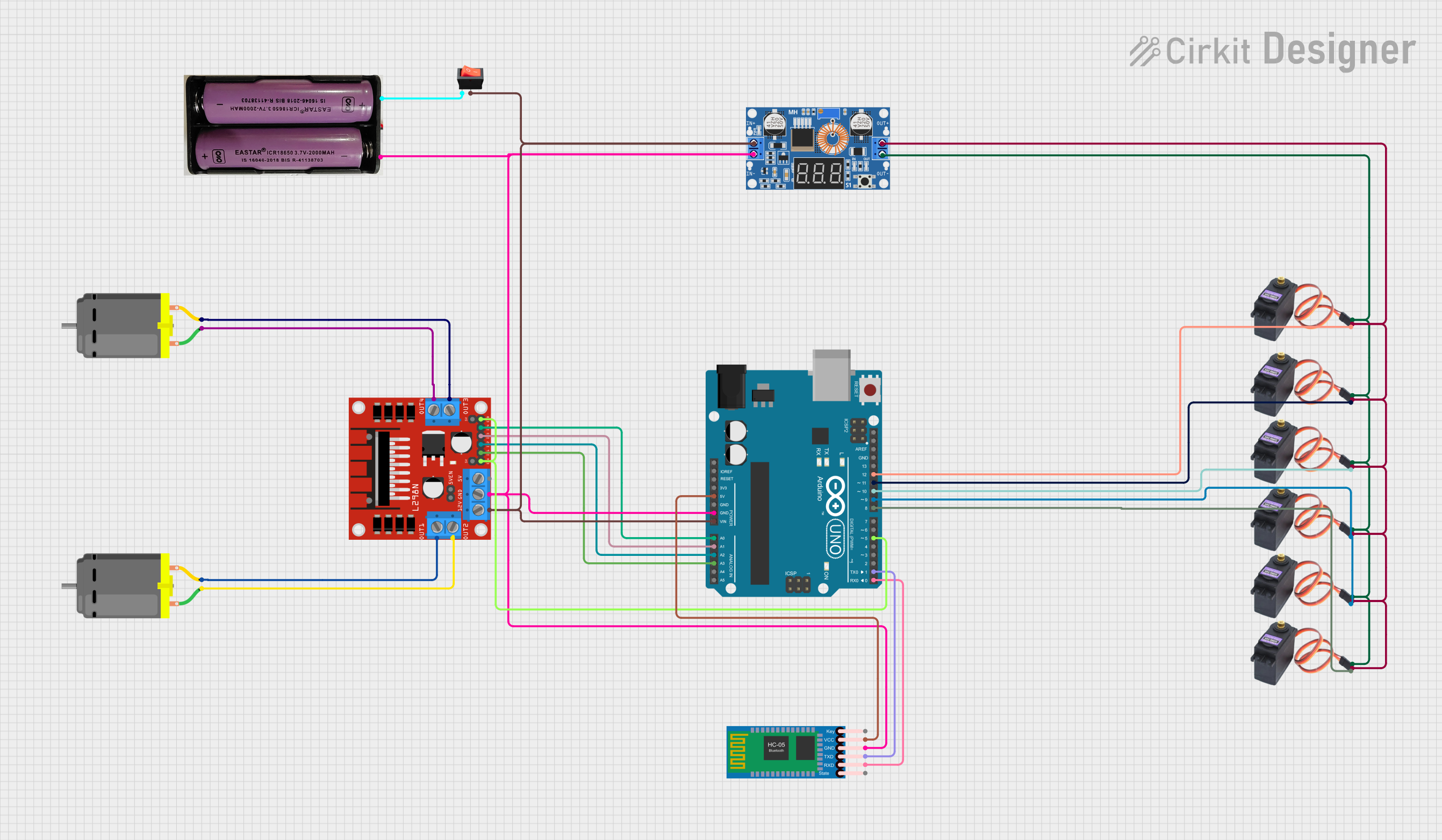
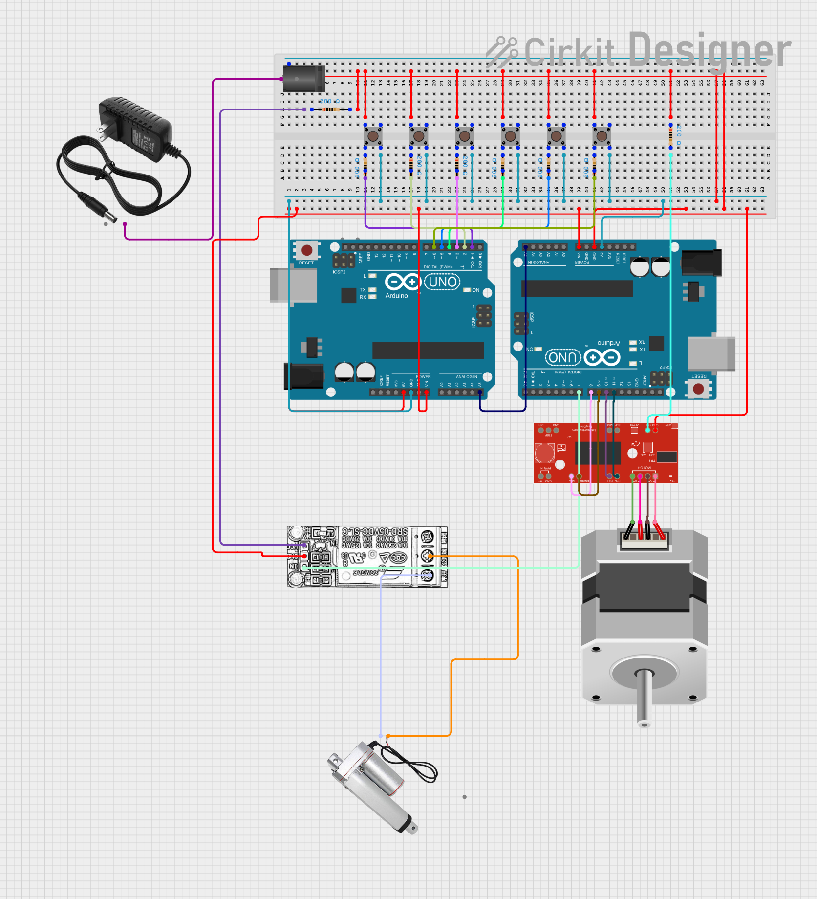
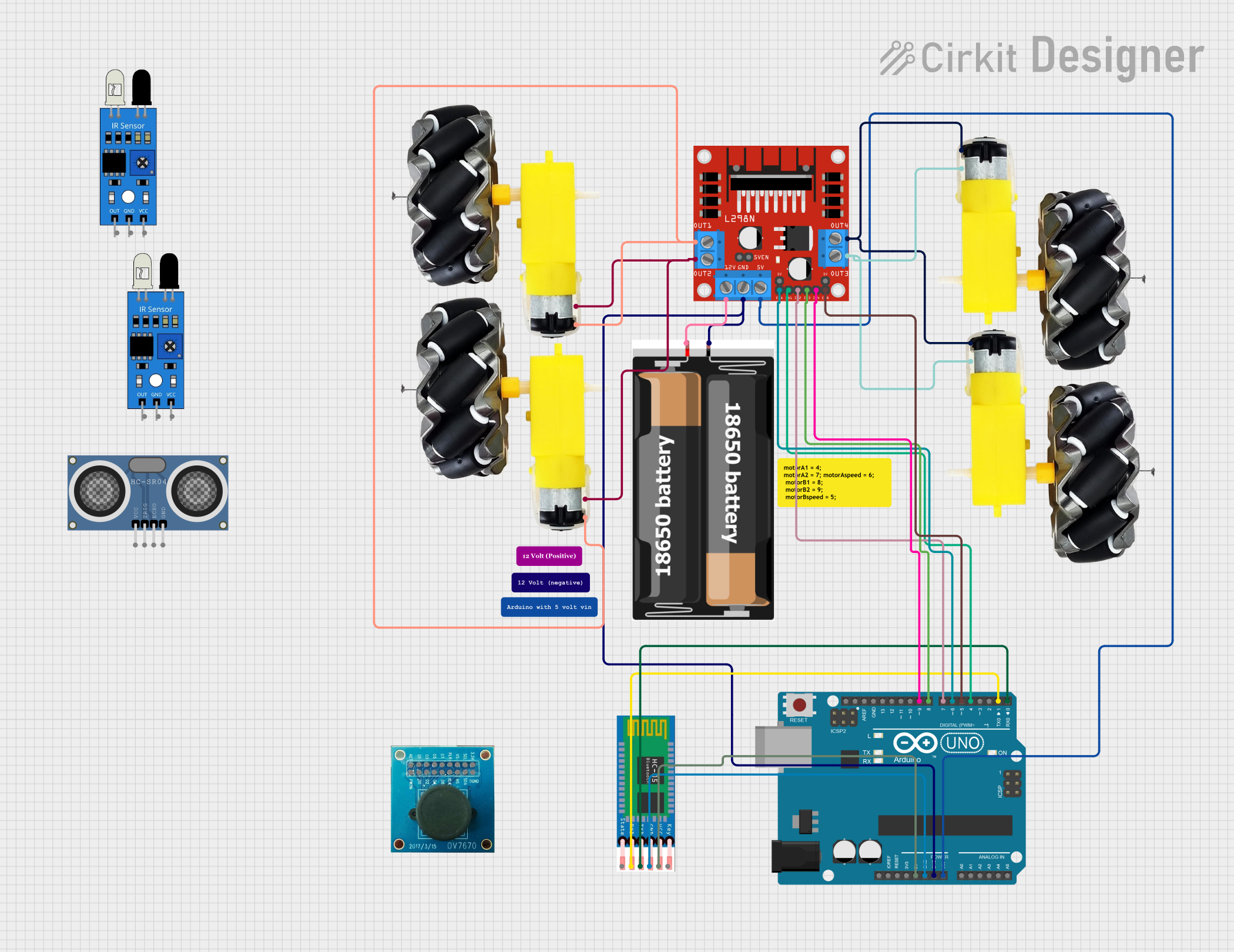
Explore Projects Built with Maker Driver
Common Applications and Use Cases
- Robotics projects requiring precise motor control
- DIY electronics projects involving DC motors
- Automated systems such as conveyor belts or small vehicles
- Educational kits for learning motor control and electronics
Technical Specifications
The following table outlines the key technical details of the Maker Driver:
| Parameter | Value |
|---|---|
| Manufacturer Part ID | MAKER-DRIVE |
| Input Voltage Range | 3.6V to 9V |
| Maximum Motor Current | 1.6A per channel (continuous) |
| Number of Channels | 2 (dual-channel motor driver) |
| Control Interface | PWM (Pulse Width Modulation) |
| Logic Voltage | 3.3V or 5V (compatible with most MCUs) |
| Dimensions | 35mm x 25mm x 10mm |
| Protection Features | Overcurrent and thermal shutdown |
Pin Configuration and Descriptions
The Maker Driver has a simple pinout for easy integration into your projects. The table below describes each pin:
| Pin Name | Type | Description |
|---|---|---|
| VM | Power Input | Motor power supply (3.6V to 9V). Connect to the positive terminal of the power source. |
| GND | Power Ground | Ground connection. Connect to the negative terminal of the power source. |
| AIN1 | Input | Control signal for Motor A direction. |
| AIN2 | Input | Control signal for Motor A direction. |
| PWMA | Input (PWM) | PWM signal for controlling Motor A speed. |
| BIN1 | Input | Control signal for Motor B direction. |
| BIN2 | Input | Control signal for Motor B direction. |
| PWMB | Input (PWM) | PWM signal for controlling Motor B speed. |
| Motor A+ | Output | Positive terminal for Motor A. |
| Motor A- | Output | Negative terminal for Motor A. |
| Motor B+ | Output | Positive terminal for Motor B. |
| Motor B- | Output | Negative terminal for Motor B. |
Usage Instructions
How to Use the Maker Driver in a Circuit
- Power Supply: Connect the VM pin to a power source (3.6V to 9V) and the GND pin to ground.
- Motor Connections: Connect the DC motors to the Motor A+/- and Motor B+/- terminals.
- Control Signals:
- Use AIN1 and AIN2 to control the direction of Motor A.
- Use BIN1 and BIN2 to control the direction of Motor B.
- Provide PWM signals to PWMA and PWMB to control the speed of Motor A and Motor B, respectively.
- Microcontroller Interface: Connect the control pins (AIN1, AIN2, BIN1, BIN2, PWMA, PWMB) to the GPIO pins of your microcontroller.
Important Considerations and Best Practices
- Ensure the power supply voltage is within the specified range (3.6V to 9V).
- Do not exceed the maximum current rating of 1.6A per channel.
- Use appropriate heat dissipation methods if the driver operates near its maximum current for extended periods.
- Double-check all connections before powering the circuit to avoid damage to the driver or motors.
Example: Using Maker Driver with Arduino UNO
Below is an example Arduino sketch to control two DC motors using the Maker Driver:
// Define control pins for Motor A
const int AIN1 = 2;  // Direction control pin 1 for Motor A
const int AIN2 = 3;  // Direction control pin 2 for Motor A
const int PWMA = 5;  // PWM speed control pin for Motor A

// Define control pins for Motor B
const int BIN1 = 4;  // Direction control pin 1 for Motor B
const int BIN2 = 7;  // Direction control pin 2 for Motor B
const int PWMB = 6;  // PWM speed control pin for Motor B

void setup() {
  // Set motor control pins as outputs
  pinMode(AIN1, OUTPUT);
  pinMode(AIN2, OUTPUT);
  pinMode(PWMA, OUTPUT);
  pinMode(BIN1, OUTPUT);
  pinMode(BIN2, OUTPUT);
  pinMode(PWMB, OUTPUT);
}

void loop() {
  // Example: Rotate Motor A forward at 50% speed
  digitalWrite(AIN1, HIGH);  // Set direction
  digitalWrite(AIN2, LOW);
  analogWrite(PWMA, 128);    // Set speed (128 = 50% duty cycle)

  // Example: Rotate Motor B backward at 75% speed
  digitalWrite(BIN1, LOW);   // Set direction
  digitalWrite(BIN2, HIGH);
  analogWrite(PWMB, 192);    // Set speed (192 = 75% duty cycle)

  delay(2000);  // Run motors for 2 seconds

  // Stop both motors
  analogWrite(PWMA, 0);
  analogWrite(PWMB, 0);

  delay(2000);  // Wait for 2 seconds before repeating
}
Troubleshooting and FAQs
Common Issues and Solutions
Motors Not Spinning:
- Ensure the power supply is connected and within the specified voltage range.
- Verify that the control signals (AIN1, AIN2, BIN1, BIN2, PWMA, PWMB) are correctly configured.
- Check motor connections to the output terminals (Motor A+/-, Motor B+/-).
Overheating:
- Ensure the current drawn by the motors does not exceed 1.6A per channel.
- Use a heat sink or active cooling if the driver operates near its maximum current for long periods.
Erratic Motor Behavior:
- Check for loose or incorrect wiring.
- Ensure the PWM signals are stable and within the correct frequency range.
FAQs
Q: Can the Maker Driver control stepper motors?
A: No, the Maker Driver is designed for DC motors only. For stepper motors, use a dedicated stepper motor driver.
Q: Is the Maker Driver compatible with 12V motors?
A: No, the maximum input voltage for the Maker Driver is 9V. Using a 12V motor may damage the driver.
Q: Can I use the Maker Driver with a Raspberry Pi?
A: Yes, the Maker Driver is compatible with Raspberry Pi. Ensure you use appropriate GPIO pins for control signals and provide a 3.3V logic level.
Q: What is the PWM frequency range supported by the Maker Driver?
A: The Maker Driver supports PWM frequencies up to 20kHz, which is suitable for most applications.