How to Use Multi-channel DC power conversion module: Examples, Pinouts, and Specs
Introduction
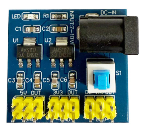
The Multi-channel DC Power Conversion Module (Manufacturer: 1, Part ID: 1) is a versatile device designed to convert and regulate multiple DC voltage levels from a single input source. This module enables efficient power distribution to various components in a circuit, making it an essential tool for projects requiring multiple voltage levels.
Explore Projects Built with Multi-channel DC power conversion module


Explore Projects Built with Multi-channel DC power conversion module
Common Applications and Use Cases
- Powering microcontrollers, sensors, and actuators in embedded systems
- Supplying multiple voltage levels in robotics and automation projects
- Providing regulated power for audio, communication, and IoT devices
- Prototyping and testing circuits with diverse voltage requirements
Technical Specifications
Key Technical Details
- Input Voltage Range: 6V to 24V DC
- Output Voltage Levels: Configurable (e.g., 3.3V, 5V, 12V)
- Maximum Output Current: 2A per channel (varies by configuration)
- Efficiency: Up to 90% (depending on load and input voltage)
- Operating Temperature: -20°C to 85°C
- Protection Features: Overcurrent, overvoltage, and thermal shutdown
- Dimensions: 50mm x 40mm x 15mm
Pin Configuration and Descriptions
The module typically features input and output terminals for power connections, as well as optional control pins for advanced functionality. Below is a standard pinout configuration:
| Pin Name | Type | Description |
|---|---|---|
| VIN | Power Input | Connect to the DC input voltage source (6V to 24V). |
| GND | Power Ground | Common ground for input and output connections. |
| VOUT1 | Power Output | Regulated output voltage channel 1 (e.g., 3.3V). |
| VOUT2 | Power Output | Regulated output voltage channel 2 (e.g., 5V). |
| VOUT3 | Power Output | Regulated output voltage channel 3 (e.g., 12V). |
| EN | Control Input | Enable pin for turning the module on/off (active high). |
| ADJ1 | Control Input | Adjustable pin for fine-tuning VOUT1 (if supported). |
| ADJ2 | Control Input | Adjustable pin for fine-tuning VOUT2 (if supported). |
| ADJ3 | Control Input | Adjustable pin for fine-tuning VOUT3 (if supported). |
Note: The exact pin configuration may vary depending on the specific model. Refer to the datasheet for detailed information.
Usage Instructions
How to Use the Component in a Circuit
- Connect the Input Voltage:
- Attach the positive terminal of your DC power source to the
VINpin. - Connect the negative terminal to the
GNDpin.
- Attach the positive terminal of your DC power source to the
- Connect the Output Loads:
- Attach the devices requiring power to the appropriate
VOUTpins (e.g., VOUT1 for 3.3V devices). - Ensure the total current draw does not exceed the maximum output current per channel.
- Attach the devices requiring power to the appropriate
- Enable the Module:
- If the module includes an
ENpin, connect it to a HIGH signal (e.g., 3.3V or 5V) to enable the outputs.
- If the module includes an
- Adjust Output Voltages (Optional):
- If adjustable pins (e.g.,
ADJ1,ADJ2) are available, use a potentiometer or resistor divider to fine-tune the output voltage.
- If adjustable pins (e.g.,
Important Considerations and Best Practices
- Input Voltage: Ensure the input voltage is within the specified range (6V to 24V) to avoid damage.
- Heat Dissipation: For high current loads, consider adding a heatsink or active cooling to prevent overheating.
- Load Balancing: Distribute the load evenly across the output channels to maximize efficiency.
- Decoupling Capacitors: Add decoupling capacitors near the output pins to reduce noise and improve stability.
- Polarity Protection: Verify the polarity of the input connections to prevent damage to the module.
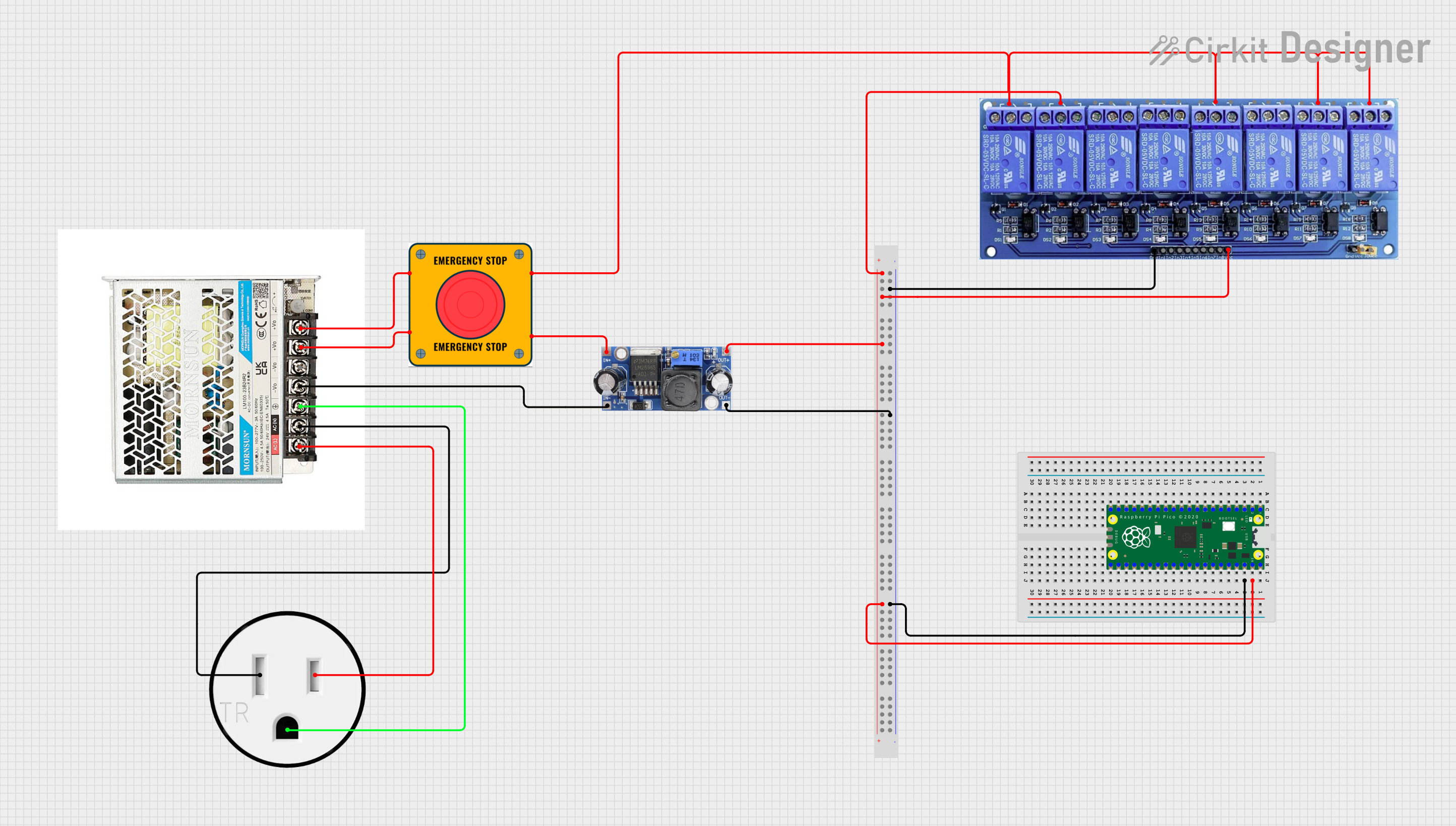
Example: Using with an Arduino UNO
The module can be used to power an Arduino UNO and additional peripherals. Below is an example circuit and code:
Circuit Connections
- Connect the module's
VINandGNDto a 12V DC power source. - Connect
VOUT1(5V) to the Arduino UNO's5Vpin. - Connect
GNDto the Arduino UNO'sGNDpin. - Use
VOUT2(3.3V) to power a 3.3V sensor.
Arduino Code Example
// Example code to read data from a 3.3V sensor powered by the module

const int sensorPin = A0; // Analog pin connected to the sensor output
int sensorValue = 0;      // Variable to store the sensor reading

void setup() {
  Serial.begin(9600); // Initialize serial communication
  pinMode(sensorPin, INPUT); // Set the sensor pin as input
}

void loop() {
  sensorValue = analogRead(sensorPin); // Read the sensor value
  Serial.print("Sensor Value: ");
  Serial.println(sensorValue); // Print the sensor value to the Serial Monitor
  delay(1000); // Wait for 1 second before the next reading
}
Note: Ensure the total current draw of the Arduino and peripherals does not exceed the module's output current rating.
Troubleshooting and FAQs
Common Issues and Solutions
No Output Voltage:
- Verify that the input voltage is within the specified range.
- Check if the
ENpin is connected to a HIGH signal (if applicable). - Inspect all connections for loose wires or incorrect polarity.
Overheating:
- Ensure the module is not overloaded. Reduce the current draw if necessary.
- Add a heatsink or improve ventilation around the module.
Voltage Instability:
- Add decoupling capacitors near the output pins to stabilize the voltage.
- Check for excessive noise or interference from nearby components.
Output Voltage Too Low or High:
- Verify the load requirements and ensure they match the module's output specifications.
- Adjust the
ADJpins (if available) to fine-tune the output voltage.
FAQs
Can I use this module with a battery as the input source? Yes, as long as the battery voltage is within the specified input range (6V to 24V).
What happens if I exceed the maximum output current? The module's overcurrent protection will activate, shutting down the output to prevent damage.
Can I use all output channels simultaneously? Yes, but ensure the total current draw does not exceed the module's overall power rating.
Is the module compatible with 24/7 operation? Yes, provided it is operated within the specified temperature and load limits.