How to Use PWM: Examples, Pinouts, and Specs
Introduction
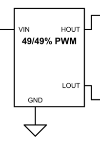
Pulse Width Modulation (PWM) is a technique used to control the amount of power delivered to an electrical load by varying the width of the pulses in a pulse train. By adjusting the duty cycle (the percentage of time the signal is "on" versus "off"), PWM enables precise control over power delivery without significant energy loss.
PWM is widely used in various applications, including:
- Motor speed control (e.g., DC motors in robotics or industrial systems)
- LED brightness control (e.g., dimming lights)
- Signal modulation (e.g., audio signal generation)
- Power regulation in switching power supplies
PWM is not a physical component but rather a method implemented in microcontrollers, integrated circuits, or dedicated PWM controllers.
Explore Projects Built with PWM
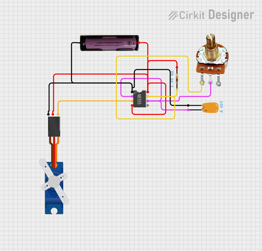

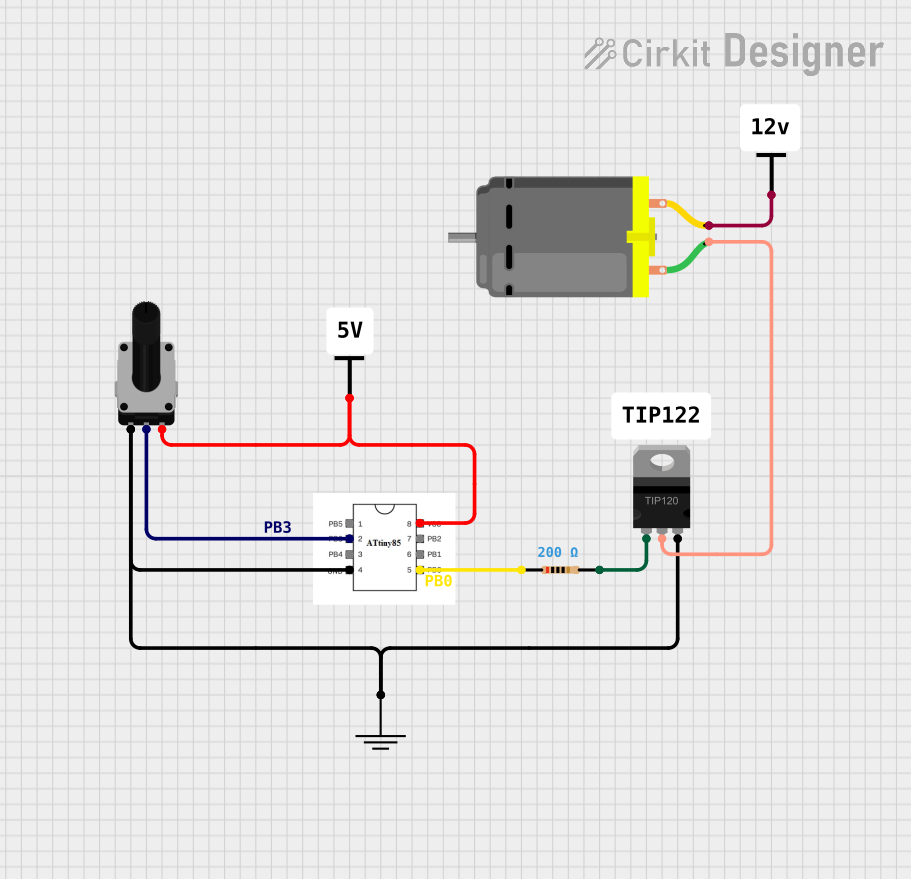

Explore Projects Built with PWM
Technical Specifications
PWM signals are characterized by the following parameters:
- Frequency: The number of cycles per second, typically measured in Hertz (Hz).
- Duty Cycle: The percentage of one cycle during which the signal is "on."
- Voltage Levels: The high and low voltage levels of the signal (e.g., 0V and 5V for digital PWM).
- Resolution: The number of discrete steps available for duty cycle adjustment, often determined by the bit depth of the PWM generator (e.g., 8-bit, 10-bit).
Example Pin Configuration for PWM on an Arduino UNO
The Arduino UNO microcontroller has several pins capable of generating PWM signals. These pins are marked with a ~ symbol on the board.
| Pin | PWM Channel | Timer Used | Notes |
|---|---|---|---|
| 3 | PWM Channel 1 | Timer 2 | Shared with Pin 11 |
| 5 | PWM Channel 2 | Timer 0 | Shared with Pin 6 |
| 6 | PWM Channel 3 | Timer 0 | Shared with Pin 5 |
| 9 | PWM Channel 4 | Timer 1 | Shared with Pin 10 |
| 10 | PWM Channel 5 | Timer 1 | Shared with Pin 9 |
| 11 | PWM Channel 6 | Timer 2 | Shared with Pin 3 |
Usage Instructions
How to Use PWM in a Circuit
- Connect the Load: Attach the load (e.g., motor, LED) to the PWM output pin. Use a transistor or MOSFET if the load requires more current than the microcontroller can supply.
- Set the Frequency: Choose an appropriate PWM frequency based on the application. For example:
- 1 kHz to 10 kHz for motor control
- 100 Hz to 1 kHz for LED dimming
- Adjust the Duty Cycle: Modify the duty cycle to control the power delivered to the load. A higher duty cycle increases power, while a lower duty cycle decreases it.
Example Code for Arduino UNO
The following example demonstrates how to use PWM to control the brightness of an LED connected to Pin 9 of an Arduino UNO.
// PWM Example: LED Brightness Control
// Connect an LED to Pin 9 with a current-limiting resistor (e.g., 220 ohms).

int pwmPin = 9; // PWM-capable pin
int brightness = 0; // Initial brightness (0-255)
int fadeAmount = 5; // Amount to change brightness

void setup() {
  pinMode(pwmPin, OUTPUT); // Set the pin as an output
}

void loop() {
  analogWrite(pwmPin, brightness); // Write PWM signal to the pin

  // Change the brightness for the next loop
  brightness = brightness + fadeAmount;

  // Reverse the direction of fading at the ends of the range
  if (brightness <= 0 || brightness >= 255) {
    fadeAmount = -fadeAmount;
  }

  delay(30); // Pause to see the fading effect
}
Important Considerations
- Power Handling: Ensure the PWM output pin or driver circuit can handle the current and voltage requirements of the load.
- Filtering: For some applications, such as audio signal generation, a low-pass filter may be required to smooth the PWM signal into an analog waveform.
- Frequency Selection: Choose a frequency that avoids audible noise (e.g., >20 kHz for motors) or flicker (e.g., >100 Hz for LEDs).
Troubleshooting and FAQs
Common Issues
Load Not Responding to PWM Signal
- Cause: Incorrect wiring or insufficient current.
- Solution: Verify connections and use a transistor or MOSFET if the load requires more current than the microcontroller can supply.
PWM Signal Causes Audible Noise
- Cause: PWM frequency is within the audible range (20 Hz to 20 kHz).
- Solution: Increase the PWM frequency to reduce noise.
LED Flickering
- Cause: PWM frequency is too low.
- Solution: Use a frequency above 100 Hz to eliminate visible flicker.
Motor Jerking or Stalling
- Cause: Duty cycle changes are too abrupt or frequency is too low.
- Solution: Gradually adjust the duty cycle and use a frequency suitable for motor control (e.g., 1 kHz to 10 kHz).
FAQs
Q: Can I use PWM to generate an analog voltage?
A: Yes, by passing the PWM signal through a low-pass filter, you can approximate an analog voltage.
Q: What is the maximum resolution of PWM on an Arduino UNO?
A: The Arduino UNO typically supports 8-bit PWM resolution, allowing 256 discrete duty cycle levels (0-255).
Q: Can I use PWM to control AC devices?
A: PWM is primarily designed for DC loads. To control AC devices, you would need additional circuitry, such as a triac-based dimmer or an inverter.
Q: How do I calculate the duty cycle?
A: Duty cycle (%) = (Time ON / Total Period) × 100. For example, if the signal is ON for 2 ms in a 10 ms period, the duty cycle is 20%.
By following this documentation, you can effectively implement PWM in your projects for precise power control and signal modulation.