How to Use RGB LED: Four Pin: Examples, Pinouts, and Specs
Introduction
An RGB LED with four pins is a versatile electronic component that combines red, green, and blue light to create a wide spectrum of colors. Each of the three colors has its own dedicated pin for control, with the fourth pin typically serving as a common cathode or anode. These LEDs are widely used in various applications such as mood lighting, displays, indicators, and decorative purposes.
Explore Projects Built with RGB LED: Four Pin
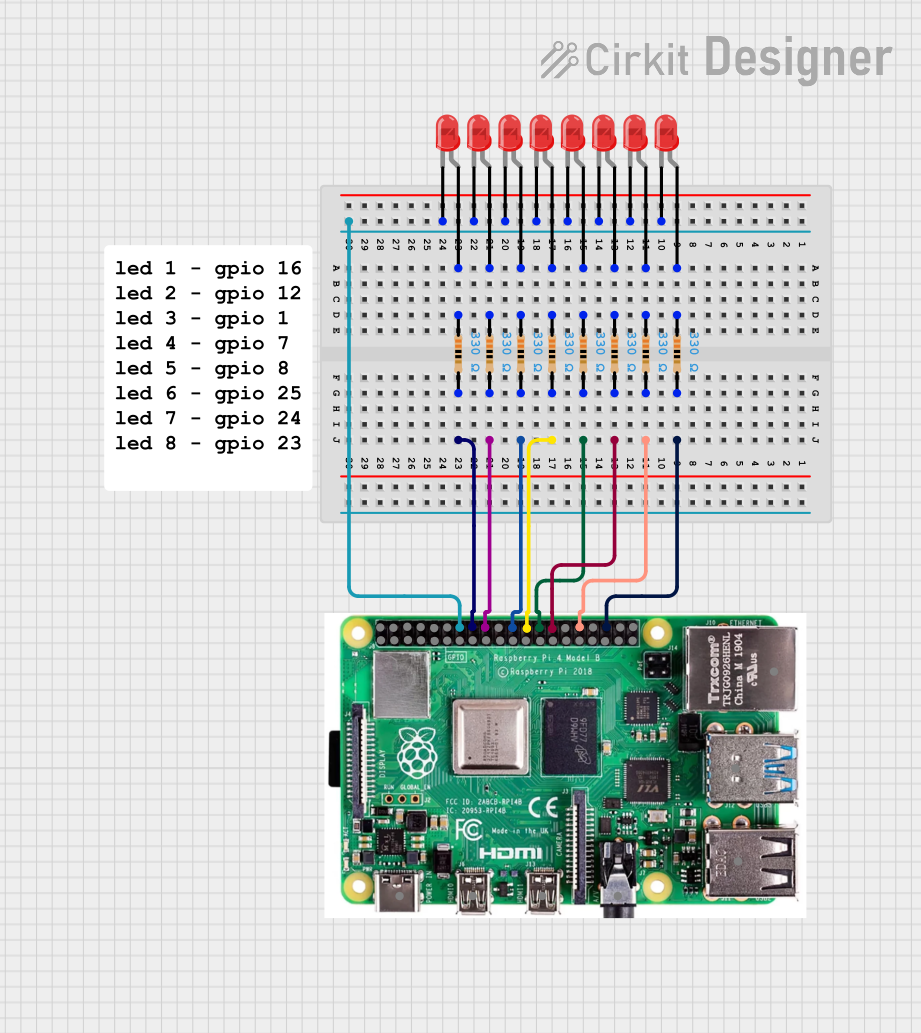
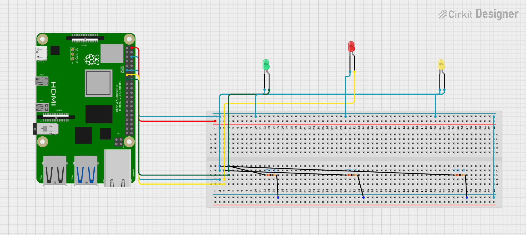
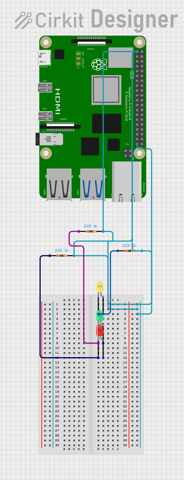
Explore Projects Built with RGB LED: Four Pin
Technical Specifications
Key Technical Details
- Forward Voltage (Typical): Red: 2.0-2.2V, Green: 3.0-3.2V, Blue: 3.0-3.2V
- Forward Current: 20mA per channel (recommended)
- Luminous Intensity: Varies by color and manufacturer
- Viewing Angle: Typically 120 degrees
Pin Configuration and Descriptions
| Pin Number | Description | Notes |
|---|---|---|
| 1 | Red Anode/Cathode | Connect to PWM pin for control |
| 2 | Green Anode/Cathode | Connect to PWM pin for control |
| 3 | Blue Anode/Cathode | Connect to PWM pin for control |
| 4 | Common Cathode/Anode | Connect to GND/VCC respectively |
Note: The configuration (common anode or cathode) will depend on the specific RGB LED model.
Usage Instructions
Connecting to a Circuit
- Identify if your RGB LED is common anode or common cathode.
- Connect the common pin (anode or cathode) to the power supply (VCC or GND).
- Connect the remaining pins (R, G, B) to PWM-capable pins on your microcontroller (e.g., Arduino UNO) through current-limiting resistors.
Best Practices
- Use current-limiting resistors to prevent damage to the LED.
- Avoid exceeding the maximum forward current and voltage ratings.
- Use pulse-width modulation (PWM) to control the brightness and color mixing.
Example Code for Arduino UNO
// Define the RGB LED pins
const int RED_PIN = 9;   // Red pin connected to PWM pin 9
const int GREEN_PIN = 10; // Green pin connected to PWM pin 10
const int BLUE_PIN = 11;  // Blue pin connected to PWM pin 11

void setup() {
  // Set the RGB LED pins as output
  pinMode(RED_PIN, OUTPUT);
  pinMode(GREEN_PIN, OUTPUT);
  pinMode(BLUE_PIN, OUTPUT);
}

void loop() {
  // Set the color to purple
  analogWrite(RED_PIN, 255);   // Red at full brightness
  analogWrite(GREEN_PIN, 0);   // Green off
  analogWrite(BLUE_PIN, 255);  // Blue at full brightness

  // Keep the color for 1 second
  delay(1000);

  // Turn off the LED
  analogWrite(RED_PIN, 0);
  analogWrite(GREEN_PIN, 0);
  analogWrite(BLUE_PIN, 0);

  // Wait for 1 second
  delay(1000);
}
Note: The above code assumes a common anode RGB LED. If using a common cathode, invert the PWM values (e.g., use analogWrite(RED_PIN, 0) for full brightness).
Troubleshooting and FAQs
Common Issues
- LED not lighting up: Ensure the common pin is correctly connected to power or ground, and that the PWM pins are properly configured.
- Incorrect colors: Verify that the pins are connected to the correct color channels and that the PWM values are set appropriately.
- Dim or flickering LED: Check for loose connections and ensure that the current-limiting resistors are of the correct value.
Solutions and Tips
- Double-check the pin configuration against the datasheet for your specific RGB LED model.
- Use a multimeter to verify connections and the presence of appropriate voltages.
- Ensure that your microcontroller's PWM frequency is suitable for driving LEDs.
FAQs
Q: Can I connect the RGB LED directly to an Arduino without resistors?
A: No, you should always use current-limiting resistors to prevent damage to both the LED and the microcontroller.
Q: How do I create different colors?
A: By varying the PWM signal to each color pin, you can mix red, green, and blue to create a wide range of colors. For example, equal brightness of all three colors will create white light.
Q: What resistor value should I use?
A: The value depends on your LED's forward voltage and desired current. A common starting point is 220 ohms for a 5V system. Use Ohm's law (V=IR) to calculate the exact value needed.