How to Use RED LED METAL: Examples, Pinouts, and Specs
Introduction
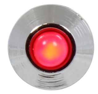
The RED LED METAL, manufactured by AC (Part ID: LED), is a red light-emitting diode encased in a durable metal housing. This component is widely used in electronic circuits for visual indication, such as power status, signal output, or as a light source. Its robust metal casing provides enhanced durability and heat dissipation, making it suitable for both consumer and industrial applications.
Explore Projects Built with RED LED METAL

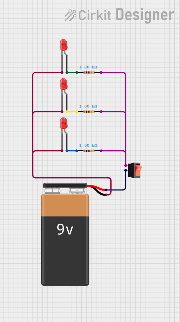
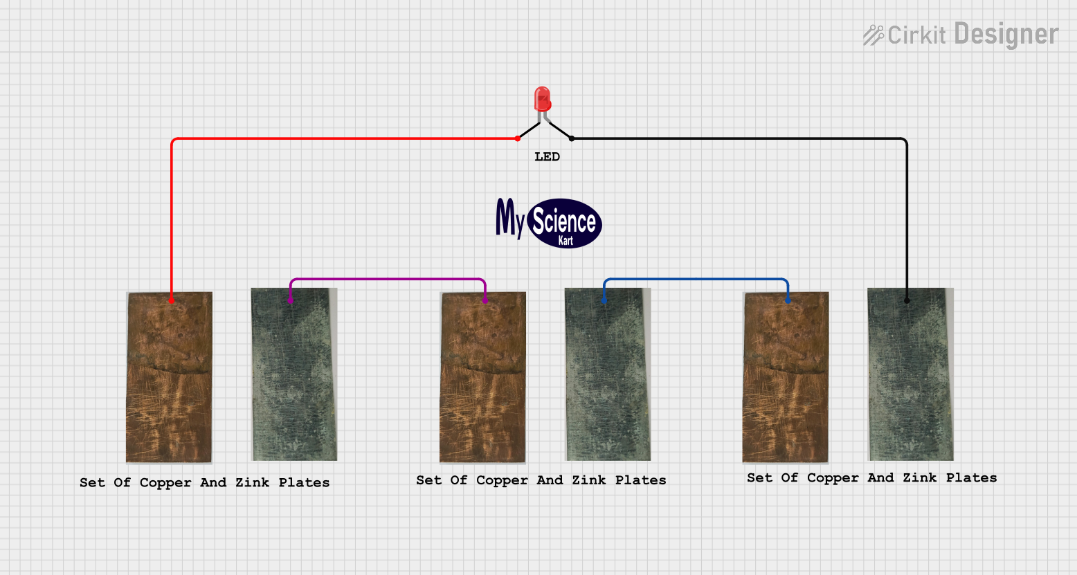
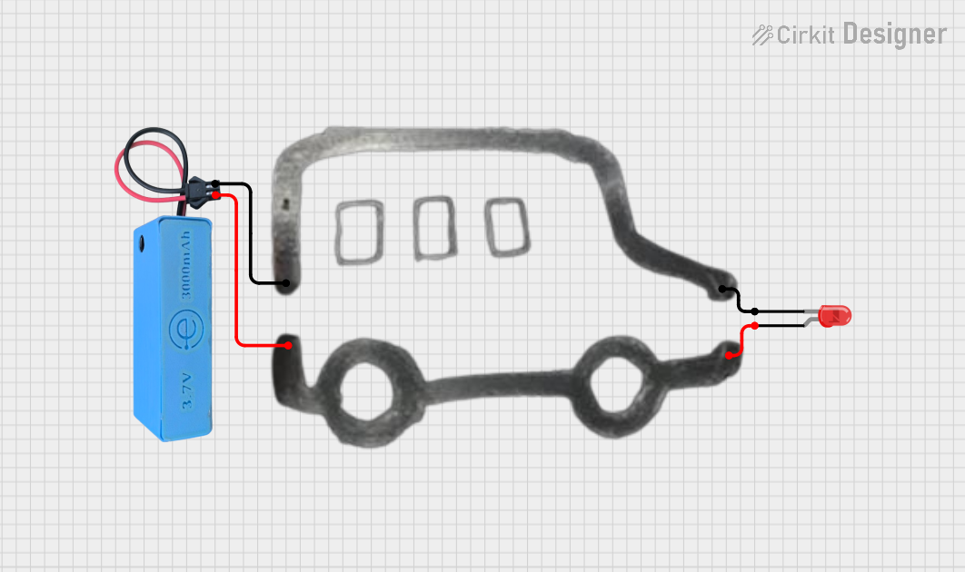
Explore Projects Built with RED LED METAL
Common Applications
- Power status indicators in electronic devices
- Signal output in control panels
- Decorative or functional lighting in projects
- Visual feedback in prototyping and testing
- Automotive and industrial equipment displays
Technical Specifications
The following table outlines the key technical details of the RED LED METAL:
| Parameter | Value |
|---|---|
| Manufacturer | AC |
| Part ID | LED |
| Forward Voltage (Vf) | 1.8V to 2.2V |
| Forward Current (If) | 20mA (typical) |
| Maximum Current (Imax) | 30mA |
| Wavelength | 620nm to 630nm (red) |
| Viewing Angle | 30° |
| Casing Material | Metal |
| Operating Temperature | -40°C to +85°C |
| Storage Temperature | -40°C to +100°C |
Pin Configuration
The RED LED METAL has two pins:
| Pin Name | Description |
|---|---|
| Anode | Positive terminal (longer pin) |
| Cathode | Negative terminal (shorter pin) |
Usage Instructions
How to Use the RED LED METAL in a Circuit
- Identify the Pins: The longer pin is the anode (positive), and the shorter pin is the cathode (negative). Ensure correct polarity when connecting the LED.
- Use a Current-Limiting Resistor: To prevent damage, always connect a resistor in series with the LED. The resistor value can be calculated using Ohm's Law:
[
R = \frac{V_{supply} - V_f}{I_f}
]
Where:
- ( V_{supply} ) is the supply voltage
- ( V_f ) is the forward voltage of the LED (1.8V to 2.2V)
- ( I_f ) is the forward current (20mA typical)
- Connect to Power Source: Connect the anode to the positive terminal of the power source (via the resistor) and the cathode to the negative terminal.
Example: Connecting to an Arduino UNO
The RED LED METAL can be easily interfaced with an Arduino UNO for basic on/off control. Below is an example circuit and code:
Circuit Setup
- Connect the anode of the LED to a digital pin on the Arduino (e.g., pin 13) through a 220Ω resistor.
- Connect the cathode to the Arduino's GND pin.
Arduino Code
// RED LED METAL Example Code
// This code blinks the RED LED METAL connected to pin 13 of the Arduino UNO.

const int ledPin = 13; // Define the pin connected to the LED

void setup() {
  pinMode(ledPin, OUTPUT); // Set the LED pin as an output
}

void loop() {
  digitalWrite(ledPin, HIGH); // Turn the LED on
  delay(1000);                // Wait for 1 second
  digitalWrite(ledPin, LOW);  // Turn the LED off
  delay(1000);                // Wait for 1 second
}
Important Considerations
- Polarity: LEDs are polarized components. Reversing the polarity can damage the LED.
- Resistor Selection: Always use an appropriate resistor to limit current and prevent overheating.
- Heat Dissipation: The metal casing helps dissipate heat, but avoid exceeding the maximum current rating.
Troubleshooting and FAQs
Common Issues
LED Does Not Light Up
- Cause: Incorrect polarity or insufficient current.
- Solution: Verify the anode and cathode connections. Check the resistor value and ensure the power supply provides sufficient voltage.
LED is Dim
- Cause: Resistor value too high or low supply voltage.
- Solution: Recalculate the resistor value and ensure the supply voltage is within the specified range.
LED Overheats
- Cause: Excessive current or insufficient heat dissipation.
- Solution: Use a higher-value resistor to limit current. Ensure proper ventilation around the LED.
FAQs
Q: Can I use the RED LED METAL without a resistor?
A: No, using the LED without a resistor can result in excessive current flow, damaging the LED.
Q: What is the maximum voltage I can apply to the LED?
A: The forward voltage range is 1.8V to 2.2V. Exceeding this range without a resistor can damage the LED.
Q: Can I use the RED LED METAL outdoors?
A: While the metal casing provides durability, the LED itself is not waterproof. Use additional protection for outdoor applications.
Q: How do I calculate the resistor value for a 5V power supply?
A: For a 5V supply and a forward voltage of 2V, the resistor value is:
[
R = \frac{5V - 2V}{20mA} = 150\Omega
]
Use the nearest standard resistor value (e.g., 150Ω or 220Ω).