How to Use HLK-PM01: Examples, Pinouts, and Specs
Introduction
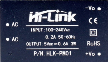
The HLK-PM01 is a compact and efficient AC-DC power module manufactured by Hi-Link. It is designed to convert an input voltage range of 85-265V AC into a stable 5V DC output, making it ideal for powering low-power electronic devices. This module is widely used in IoT devices, home automation systems, embedded systems, and other applications requiring a reliable and compact power supply.
Explore Projects Built with HLK-PM01


Explore Projects Built with HLK-PM01
Common Applications
- IoT devices and smart home systems
- Microcontroller-based projects (e.g., Arduino, ESP8266, ESP32)
- Low-power embedded systems
- Industrial control systems
- LED lighting and small appliances
Technical Specifications
The HLK-PM01 is designed to provide a stable and efficient power supply with built-in safety features. Below are its key technical details:
| Parameter | Value |
|---|---|
| Input Voltage Range | 85-265V AC |
| Output Voltage | 5V DC |
| Output Current | 600mA (maximum) |
| Output Power | 3W |
| Efficiency | ≥70% |
| Operating Temperature | -20°C to +60°C |
| Storage Temperature | -40°C to +80°C |
| Overcurrent Protection | Yes |
| Overvoltage Protection | Yes |
| Dimensions | 35mm x 18mm x 15mm |
| Weight | ~15g |
Pin Configuration and Descriptions
The HLK-PM01 module has six pins, divided into two groups: AC input and DC output. Below is the pin configuration:
| Pin Number | Pin Name | Description |
|---|---|---|
| 1 | AC(N) | AC input (Neutral) |
| 2 | AC(L) | AC input (Live) |
| 3 | NC | Not connected (leave unconnected) |
| 4 | +5V | DC output (positive terminal, 5V) |
| 5 | GND | DC output (ground terminal) |
| 6 | NC | Not connected (leave unconnected) |
Note: Pins 3 and 6 are not connected internally and should be left unconnected in your circuit.
Usage Instructions
How to Use the HLK-PM01 in a Circuit
AC Input Connection:
- Connect the AC(N) pin to the neutral wire of the AC mains.
- Connect the AC(L) pin to the live wire of the AC mains.
- Ensure proper insulation and safety precautions when working with high-voltage AC.
DC Output Connection:
- Connect the +5V pin to the positive terminal of your load or circuit.
- Connect the GND pin to the ground terminal of your load or circuit.
Mounting and Insulation:
- Mount the module securely on a PCB or enclosure.
- Use proper insulation to prevent accidental contact with high-voltage pins.
Filtering and Decoupling:
- Add a capacitor (e.g., 470µF electrolytic capacitor) across the output terminals to reduce noise and improve stability.
- Optionally, add an EMI filter on the AC input side for better performance in noisy environments.
Important Considerations and Best Practices
- Safety First: Always handle the module with care when working with AC mains. Ensure proper insulation and avoid touching live wires.
- Load Requirements: Do not exceed the maximum output current of 600mA to prevent damage to the module.
- Ventilation: Ensure adequate ventilation around the module to prevent overheating.
- Testing: Test the module with a multimeter before connecting it to your final circuit to verify proper operation.
Example: Using HLK-PM01 with Arduino UNO
The HLK-PM01 can be used to power an Arduino UNO directly. Below is an example circuit and code:
Circuit Diagram
- Connect the +5V output of the HLK-PM01 to the 5V pin of the Arduino UNO.
- Connect the GND output of the HLK-PM01 to the GND pin of the Arduino UNO.
- Ensure the AC input is properly connected and insulated.
Arduino Code Example
// Example code to blink an LED using Arduino UNO powered by HLK-PM01
// Ensure proper insulation and safety when working with AC mains.

const int ledPin = 13; // Built-in LED pin on Arduino UNO

void setup() {
  pinMode(ledPin, OUTPUT); // Set LED pin as output
}

void loop() {
  digitalWrite(ledPin, HIGH); // Turn the LED on
  delay(1000);                // Wait for 1 second
  digitalWrite(ledPin, LOW);  // Turn the LED off
  delay(1000);                // Wait for 1 second
}
Warning: Always ensure the HLK-PM01 is properly insulated and mounted when working with AC mains to avoid electrical hazards.
Troubleshooting and FAQs
Common Issues and Solutions
| Issue | Possible Cause | Solution |
|---|---|---|
| No output voltage | Incorrect AC input connection | Verify AC(N) and AC(L) connections. |
| Output voltage is unstable or noisy | Insufficient filtering on the output | Add a 470µF capacitor across the output pins. |
| Module overheating | Exceeding maximum load current | Reduce the load to ≤600mA. |
| Arduino not powering on | Loose or incorrect connections | Check and secure all connections. |
FAQs
Can the HLK-PM01 power a Raspberry Pi?
- No, the HLK-PM01 provides a maximum current of 600mA, which is insufficient for most Raspberry Pi models.
Is the HLK-PM01 safe for long-term use?
- Yes, the module is designed for long-term use with built-in overcurrent and overvoltage protection. However, ensure proper insulation and ventilation.
Can I use the HLK-PM01 with a 12V DC output?
- No, the HLK-PM01 is specifically designed for a 5V DC output. For 12V output, consider other Hi-Link modules like the HLK-PM12.
By following the guidelines and best practices outlined in this documentation, you can safely and effectively integrate the HLK-PM01 into your projects.