
How to Use NEMA23: Examples, Pinouts, and Specs
 Design with NEMA23 in Cirkit Designer
Introduction
The NEMA23 stepper motor is a high-performance electric motor widely used in applications requiring precise positioning and control. It is characterized by its 2.3-inch square faceplate and high torque output, making it ideal for demanding tasks. This motor is commonly found in CNC machines, 3D printers, robotics, and other automated systems where accuracy and reliability are critical.
Explore Projects Built with NEMA23
 Open Project in Cirkit Designer
 Open Project in Cirkit Designer
 Open Project in Cirkit Designer
 Open Project in Cirkit Designer
Explore Projects Built with NEMA23
Open Project in Cirkit DesignerOpen Project in Cirkit DesignerOpen Project in Cirkit DesignerOpen Project in Cirkit DesignerCommon Applications:
- CNC machines for precise cutting, milling, and engraving
- 3D printers for accurate layer-by-layer material deposition
- Robotics for controlled movement and positioning
- Conveyor systems for stepwise motion
- Automated camera sliders and gimbals
Technical Specifications
Below are the key technical details of a standard NEMA23 stepper motor. Note that specific models may vary slightly, so always refer to the datasheet of your particular motor.
General Specifications:
| Parameter | Value |
|---|---|
| Frame Size | 2.3 inches (57.15 mm) |
| Step Angle | 1.8° (200 steps per revolution) |
| Holding Torque | 0.9 Nm to 3.0 Nm (varies by model) |
| Rated Voltage | 2.8V to 4.2V (varies by model) |
| Rated Current | 1.5A to 3.0A per phase |
| Number of Phases | 2 |
| Shaft Diameter | 6.35 mm (standard) |
| Weight | ~1.1 kg (varies by model) |
Pin Configuration:
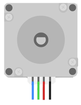
The NEMA23 stepper motor typically has four wires for bipolar operation. The table below describes the wire connections:
| Wire Color | Function | Description |
|---|---|---|
| Red | Coil A+ | Positive terminal of Coil A |
| Blue | Coil A- | Negative terminal of Coil A |
| Green | Coil B+ | Positive terminal of Coil B |
| Black | Coil B- | Negative terminal of Coil B |
Note: Some NEMA23 motors may have six or eight wires for unipolar or bipolar configurations. Always check the datasheet for your specific motor.
Usage Instructions
How to Use the NEMA23 in a Circuit:
- Power Supply: Ensure the power supply matches the motor's voltage and current ratings. Use a stepper motor driver to regulate current and protect the motor.
- Driver Connection: Connect the motor to a compatible stepper motor driver (e.g., A4988, DRV8825, or TB6600). Match the motor wires to the driver's output terminals (A+, A-, B+, B-).
- Microcontroller Interface: Use a microcontroller (e.g., Arduino UNO) to send step and direction signals to the driver. The driver will translate these signals into precise motor movements.
- Step Angle Control: Adjust the microstepping settings on the driver to achieve finer resolution if needed.
Important Considerations:
- Current Limiting: Set the current limit on the driver to prevent overheating or damage to the motor.
- Heat Management: NEMA23 motors can get hot during operation. Ensure proper ventilation or use a heatsink if necessary.
- Backlash and Coupling: Use high-quality couplers and minimize mechanical backlash for accurate motion.
- Power Down: Avoid disconnecting the motor while powered to prevent damage to the driver or motor.
Example Code for Arduino UNO:
Below is an example of controlling a NEMA23 stepper motor using an Arduino UNO and a TB6600 driver.
// Example: Controlling NEMA23 Stepper Motor with Arduino UNO and TB6600 Driver

#define STEP_PIN 3  // Pin connected to the STEP input of the driver
#define DIR_PIN 4   // Pin connected to the DIR input of the driver
#define ENABLE_PIN 5 // Pin connected to the ENABLE input of the driver

void setup() {
  pinMode(STEP_PIN, OUTPUT);  // Set STEP pin as output
  pinMode(DIR_PIN, OUTPUT);   // Set DIR pin as output
  pinMode(ENABLE_PIN, OUTPUT); // Set ENABLE pin as output

  digitalWrite(ENABLE_PIN, LOW); // Enable the driver (LOW = enabled)
}

void loop() {
  digitalWrite(DIR_PIN, HIGH); // Set direction (HIGH = clockwise)

  for (int i = 0; i < 200; i++) { // Rotate one full revolution (200 steps)
    digitalWrite(STEP_PIN, HIGH); // Generate a step pulse
    delayMicroseconds(500);       // Pulse duration (adjust for speed)
    digitalWrite(STEP_PIN, LOW);  // End of step pulse
    delayMicroseconds(500);       // Delay before next pulse
  }

  delay(1000); // Wait 1 second before reversing direction

  digitalWrite(DIR_PIN, LOW); // Set direction (LOW = counterclockwise)

  for (int i = 0; i < 200; i++) { // Rotate one full revolution in reverse
    digitalWrite(STEP_PIN, HIGH);
    delayMicroseconds(500);
    digitalWrite(STEP_PIN, LOW);
    delayMicroseconds(500);
  }

  delay(1000); // Wait 1 second before repeating
}
Notes:
- Adjust the
delayMicroseconds()value to control the motor speed. - Ensure the current limit on the TB6600 driver is set correctly for your motor.
Troubleshooting and FAQs
Common Issues:
Motor Not Moving:
- Check all connections between the motor, driver, and microcontroller.
- Ensure the power supply is adequate and properly connected.
- Verify that the driver is enabled (ENABLE pin set to LOW).
Motor Vibrates but Doesn't Rotate:
- Check the wiring of the motor coils. Incorrect wiring can cause improper operation.
- Ensure the step and direction signals are being sent correctly.
Motor Overheating:
- Verify that the current limit on the driver is set correctly.
- Provide adequate cooling or ventilation.
Skipping Steps or Inaccurate Movement:
- Reduce the motor speed or acceleration in your code.
- Check for mechanical issues such as loose couplings or excessive load.
FAQs:
Q: Can I use a NEMA23 motor with a 12V power supply?
A: Yes, but ensure the driver regulates the current to match the motor's rated current. Higher voltages (e.g., 24V or 36V) are often preferred for better performance.
Q: How do I identify the motor's coil pairs?
A: Use a multimeter to measure resistance between wires. Wires with measurable resistance belong to the same coil.
Q: Can I run the motor without a driver?
A: No, a stepper motor driver is essential for proper operation and to prevent damage to the motor or microcontroller.
By following this documentation, you can effectively integrate and operate a NEMA23 stepper motor in your projects.