How to Use Sparkfun Qwiic I2C Mux 8-kan: Examples, Pinouts, and Specs
Introduction
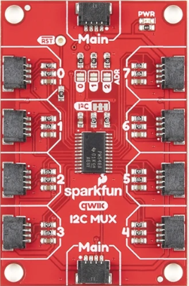
The Sparkfun Qwiic I2C Mux 8-kan is a versatile I2C multiplexer designed to simplify communication with multiple I2C devices on a single bus. It allows up to eight I2C devices to be connected without address conflicts, making it an essential tool for projects involving multiple sensors, displays, or other I2C peripherals. By dynamically switching between different I2C channels, this component ensures seamless communication and eliminates the need for manual reconfiguration of device addresses.
Explore Projects Built with Sparkfun Qwiic I2C Mux 8-kan


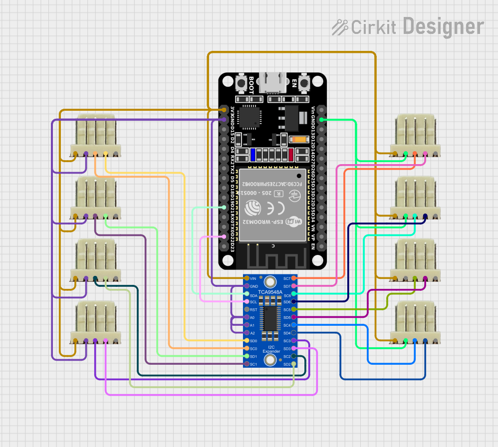

Explore Projects Built with Sparkfun Qwiic I2C Mux 8-kan
Common Applications and Use Cases
- Connecting multiple I2C devices with identical addresses to a single microcontroller.
- Expanding the I2C bus for complex projects with multiple peripherals.
- Prototyping and testing I2C devices in development environments.
- Robotics, IoT, and data acquisition systems requiring multiple sensors.
Technical Specifications
The following table outlines the key technical details of the Sparkfun Qwiic I2C Mux 8-kan:
| Parameter | Value |
|---|---|
| Manufacturer | Sparkfun |
| Part ID | Sparkfun Qwiic I2C Mux 8-kan |
| Operating Voltage | 3.3V (Qwiic-compatible) |
| Communication Protocol | I2C |
| Default I2C Address | 0x70 (modifiable via solder jumpers) |
| Number of Channels | 8 |
| Maximum I2C Speed | 400 kHz (Fast Mode) |
| Dimensions | 1.0" x 1.0" (25.4mm x 25.4mm) |
Pin Configuration and Descriptions
The Sparkfun Qwiic I2C Mux 8-kan features the following pinout:
| Pin Name | Description |
|---|---|
| GND | Ground connection |
| 3.3V | Power supply input (3.3V) |
| SDA | I2C data line (shared across all channels) |
| SCL | I2C clock line (shared across all channels) |
| Channel 0-7 | Individual I2C channels for connecting peripherals |
Usage Instructions
How to Use the Component in a Circuit
- Power the Mux: Connect the 3.3V and GND pins to your microcontroller or power supply.
- Connect the I2C Bus: Attach the SDA and SCL lines from your microcontroller to the corresponding pins on the Mux.
- Connect I2C Devices: Attach up to eight I2C devices to the individual channels (0-7). Each channel has its own SDA and SCL lines.
- Select a Channel: Use I2C commands to select the desired channel for communication. Only one channel can be active at a time.
Important Considerations and Best Practices
- Address Conflicts: Ensure that devices on different channels do not share the same address, as only one channel is active at a time.
- Pull-Up Resistors: The Qwiic system includes built-in pull-up resistors. If you're not using Qwiic connectors, ensure proper pull-up resistors are in place.
- I2C Address: The default address of the Mux is 0x70. If multiple Mux boards are used, modify the address using the solder jumpers on the board.
Example Code for Arduino UNO
Below is an example of how to use the Sparkfun Qwiic I2C Mux 8-kan with an Arduino UNO to communicate with a device on channel 0:
#include <Wire.h>

#define MUX_ADDRESS 0x70  // Default I2C address of the Mux

void selectMuxChannel(uint8_t channel) {
  // Ensure the channel is within the valid range (0-7)
  if (channel > 7) return;

  Wire.beginTransmission(MUX_ADDRESS);
  Wire.write(1 << channel);  // Select the desired channel
  Wire.endTransmission();
}

void setup() {
  Wire.begin();  // Initialize I2C communication
  Serial.begin(9600);  // Start serial communication for debugging

  Serial.println("Initializing Sparkfun Qwiic I2C Mux...");
  selectMuxChannel(0);  // Select channel 0
  Serial.println("Channel 0 selected.");
}

void loop() {
  // Example: Communicate with a device on channel 0
  Wire.beginTransmission(0x40);  // Replace 0x40 with your device's address
  Wire.write(0x00);  // Example command
  Wire.endTransmission();

  delay(1000);  // Wait for 1 second
}
Troubleshooting and FAQs
Common Issues and Solutions
Devices Not Responding:
- Ensure the correct channel is selected using the
selectMuxChannel()function. - Verify that the I2C address of the device matches the one used in your code.
- Ensure the correct channel is selected using the
Address Conflicts:
- If multiple devices share the same address, connect them to different channels on the Mux.
No Communication:
- Check the wiring and ensure proper connections for SDA, SCL, 3.3V, and GND.
- Verify that the Mux is powered and the I2C bus is functioning.
Multiple Mux Boards:
- If using multiple Mux boards, ensure each has a unique I2C address by modifying the solder jumpers.
FAQs
Can I use this Mux with 5V systems?
- The Mux is designed for 3.3V systems. If using a 5V microcontroller, use level shifters to avoid damage.
How do I modify the I2C address?
- Adjust the solder jumpers on the board to change the default address (0x70). Refer to the Sparkfun datasheet for details.
Can I activate multiple channels simultaneously?
- No, only one channel can be active at a time. This ensures proper communication without conflicts.
By following this documentation, you can effectively integrate the Sparkfun Qwiic I2C Mux 8-kan into your projects and resolve common issues with ease.