
How to Use Electronic Speed Controller(ESC): Examples, Pinouts, and Specs
 Design with Electronic Speed Controller(ESC) in Cirkit Designer
Introduction
An Electronic Speed Controller (ESC) is a critical component used to regulate the speed, direction, and braking of an electric motor. It is commonly found in applications such as radio-controlled vehicles, drones, electric skateboards, and other devices requiring precise motor control. The ESC receives input signals from a controller (e.g., a radio receiver or microcontroller) and adjusts the power delivered to the motor accordingly. This enables smooth acceleration, deceleration, and directional changes.
Explore Projects Built with Electronic Speed Controller(ESC)
 Open Project in Cirkit Designer
 Open Project in Cirkit Designer
 Open Project in Cirkit Designer
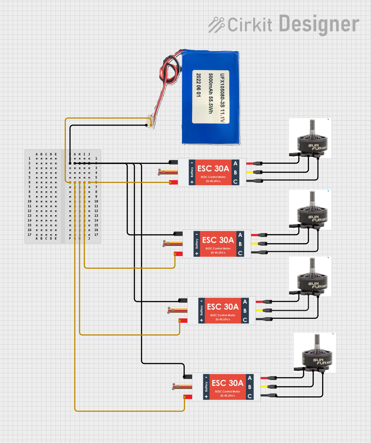 Open Project in Cirkit Designer
Explore Projects Built with Electronic Speed Controller(ESC)
Open Project in Cirkit DesignerOpen Project in Cirkit DesignerOpen Project in Cirkit DesignerOpen Project in Cirkit DesignerCommon Applications
- Drones and quadcopters for motor speed synchronization
- Radio-controlled cars, boats, and airplanes
- Electric skateboards and scooters
- Robotics and automation systems
- Industrial motor control applications
Technical Specifications
Below are the general technical specifications for a typical ESC. Note that specific values may vary depending on the model and manufacturer.
Key Technical Details
- Input Voltage Range: 6V to 22.2V (2S to 6S LiPo batteries)
- Continuous Current Rating: 20A to 120A (varies by model)
- Peak Current Rating: 30A to 150A (for short durations)
- Supported Motor Types: Brushless DC (BLDC) motors
- Signal Input: Pulse Width Modulation (PWM) signal (typically 1ms to 2ms pulse width)
- BEC (Battery Eliminator Circuit): 5V or 6V output for powering external devices (optional, depending on the ESC)
- Operating Temperature: -10°C to 80°C
- Weight: 10g to 50g (varies by model)
Pin Configuration and Descriptions
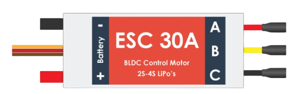
The ESC typically has three main sets of connections: motor wires, power input, and signal input. Below is a table describing these connections.
| Pin/Wire | Description |
|---|---|
| Motor Wires (A, B, C) | Three wires connected to the brushless motor for phase control. |
| Power Input (+, -) | Two wires (positive and negative) connected to the battery. |
| Signal Wire | Receives PWM signal from the controller (e.g., receiver or microcontroller). |
| BEC Output (optional) | Provides regulated 5V or 6V power for external devices like servos or receivers. |
Usage Instructions
How to Use the ESC in a Circuit
- Connect the Motor: Attach the three motor wires (A, B, C) from the ESC to the brushless motor. If the motor spins in the wrong direction, swap any two of these wires.
- Connect the Power Source: Connect the ESC's power input wires to a compatible battery (e.g., LiPo). Ensure the voltage and current ratings of the battery match the ESC's specifications.
- Connect the Signal Wire: Attach the signal wire to the PWM output pin of your controller (e.g., Arduino, RC receiver).
- Calibrate the ESC: Many ESCs require calibration to match the throttle range of the controller. Follow the manufacturer's instructions for calibration.
- Test the Setup: Power on the system and test the motor's response to throttle input. Ensure all connections are secure and the motor operates smoothly.
Important Considerations
- Battery Compatibility: Always use a battery within the ESC's voltage range to avoid damage.
- Cooling: Ensure proper ventilation or cooling, especially for high-current applications, to prevent overheating.
- Signal Input: Use a clean and stable PWM signal to avoid erratic motor behavior.
- Safety: Disconnect the battery when making adjustments to prevent accidental motor activation.
Example Code for Arduino UNO
Below is an example of how to control an ESC using an Arduino UNO. This code generates a PWM signal to adjust the motor speed.
#include <Servo.h> // Include the Servo library to generate PWM signals

Servo esc; // Create a Servo object to control the ESC

void setup() {
  esc.attach(9); // Attach the ESC signal wire to pin 9 on the Arduino
  esc.writeMicroseconds(1000); // Set initial throttle to minimum (1000us)
  delay(2000); // Wait for 2 seconds to allow the ESC to initialize
}

void loop() {
  // Gradually increase throttle from minimum (1000us) to maximum (2000us)
  for (int throttle = 1000; throttle <= 2000; throttle += 10) {
    esc.writeMicroseconds(throttle); // Send throttle signal to ESC
    delay(50); // Wait 50ms between each step
  }

  delay(2000); // Hold maximum throttle for 2 seconds

  // Gradually decrease throttle back to minimum
  for (int throttle = 2000; throttle >= 1000; throttle -= 10) {
    esc.writeMicroseconds(throttle); // Send throttle signal to ESC
    delay(50); // Wait 50ms between each step
  }

  delay(2000); // Hold minimum throttle for 2 seconds
}
Troubleshooting and FAQs
Common Issues and Solutions
Motor Does Not Spin:
- Check all connections (motor wires, power input, and signal wire).
- Ensure the battery is charged and within the ESC's voltage range.
- Verify that the ESC is receiving a valid PWM signal.
Motor Spins in the Wrong Direction:
- Swap any two of the three motor wires (A, B, C) to reverse the motor's direction.
ESC Overheats:
- Ensure proper ventilation or add a heatsink to the ESC.
- Check that the motor and battery are within the ESC's current and voltage ratings.
Erratic Motor Behavior:
- Verify that the PWM signal is stable and within the expected range (1ms to 2ms).
- Check for loose or damaged wires.
FAQs
Can I use an ESC with a brushed motor? No, ESCs designed for brushless motors are not compatible with brushed motors. Use a brushed motor ESC instead.
What happens if I exceed the ESC's current rating? Exceeding the current rating can cause the ESC to overheat, shut down, or become permanently damaged.
Do I need to calibrate the ESC every time I use it? No, calibration is typically only required during the initial setup or if you change the controller.
Can I power other devices using the ESC's BEC output? Yes, if your ESC has a BEC, you can use it to power devices like servos or receivers, provided the current draw does not exceed the BEC's rating.