How to Use tdk invensense ics-40214: Examples, Pinouts, and Specs
Introduction
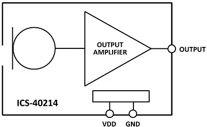
The TDK InvenSense ICS-40214 is a high-performance digital MEMS (Micro-Electro-Mechanical Systems) microphone designed for audio applications. It features low power consumption, a high signal-to-noise ratio (SNR), and excellent sensitivity, making it ideal for voice recognition, sound capture, and audio processing in portable devices. Its compact size and robust performance make it a popular choice for smartphones, tablets, IoT devices, and other consumer electronics.
Explore Projects Built with tdk invensense ics-40214

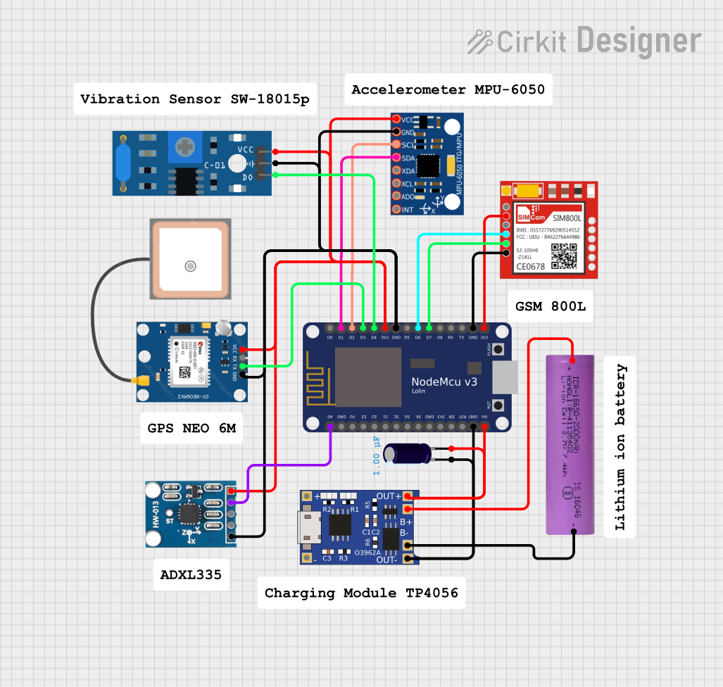
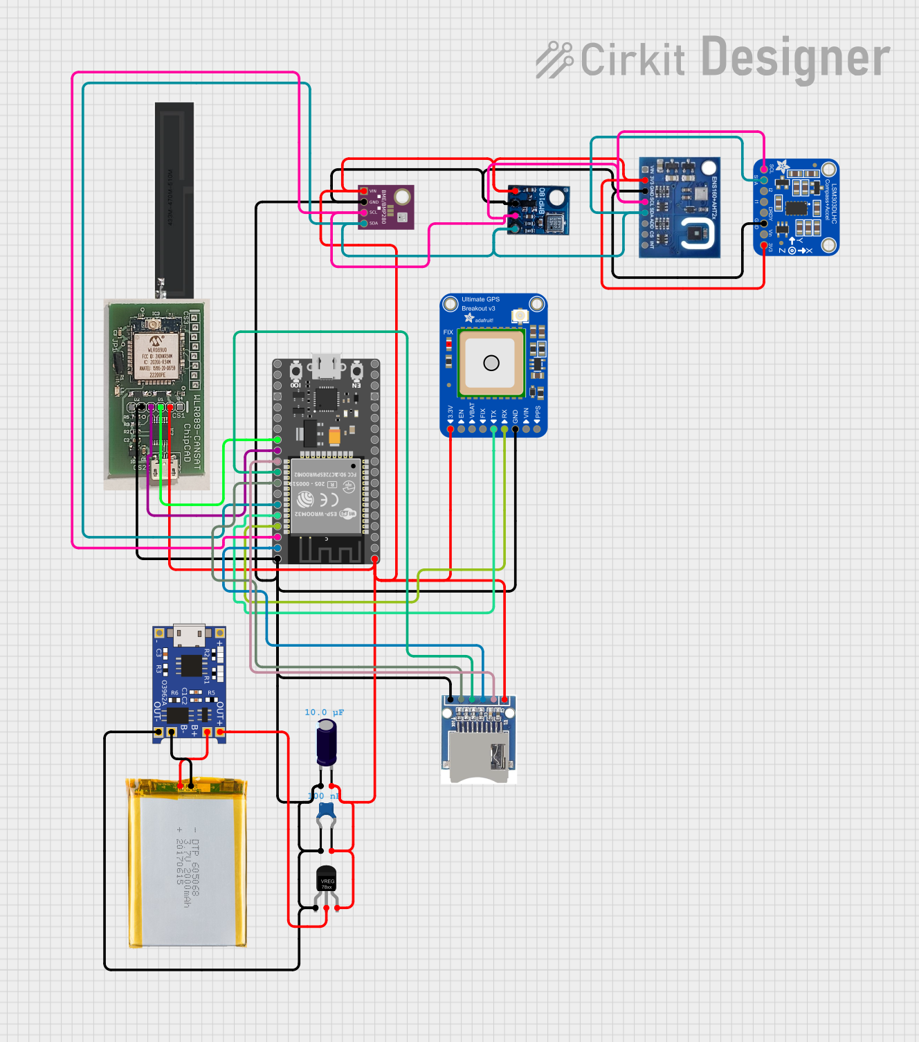

Explore Projects Built with tdk invensense ics-40214
Common Applications and Use Cases
- Voice recognition systems (e.g., smart assistants)
- Audio recording in portable devices
- Noise cancellation systems
- IoT devices with sound detection capabilities
- Wearable devices and hearing aids
Technical Specifications
Key Technical Details
| Parameter | Value |
|---|---|
| Supply Voltage (VDD) | 1.62V to 3.6V |
| Signal-to-Noise Ratio (SNR) | 65 dB |
| Sensitivity | -26 dBFS ±1 dB |
| Power Supply Rejection (PSR) | -80 dBFS |
| Current Consumption | 170 µA (typical) |
| Output Format | Pulse Density Modulation (PDM) |
| Operating Temperature Range | -40°C to +85°C |
| Package Dimensions | 3.50 mm × 2.65 mm × 0.98 mm |
Pin Configuration and Descriptions
The ICS-40214 has a 5-pin configuration. Below is the pinout and description:
| Pin Number | Pin Name | Description |
|---|---|---|
| 1 | VDD | Power supply input (1.62V to 3.6V). |
| 2 | GND | Ground connection. |
| 3 | CLK | Clock input for PDM interface. |
| 4 | DATA | Digital audio output in PDM format. |
| 5 | SEL | Channel select pin (used to configure the microphone as left or right). |
Usage Instructions
How to Use the ICS-40214 in a Circuit
- Power Supply: Connect the VDD pin to a stable power source within the range of 1.62V to 3.6V. Connect the GND pin to the ground of the circuit.
- Clock Signal: Provide a clock signal (typically 1 MHz to 3.25 MHz) to the CLK pin. This clock drives the PDM output.
- PDM Output: The DATA pin outputs the digital audio signal in PDM format. Connect this pin to a microcontroller or audio processor capable of decoding PDM signals.
- Channel Selection: Use the SEL pin to configure the microphone as either the left or right channel:
- Connect SEL to GND for the left channel.
- Connect SEL to VDD for the right channel.
Important Considerations and Best Practices
- Decoupling Capacitor: Place a 0.1 µF decoupling capacitor close to the VDD pin to reduce noise and ensure stable operation.
- Clock Signal Quality: Ensure the clock signal is clean and within the specified frequency range to avoid audio distortion.
- PCB Layout: Minimize the trace length for the CLK and DATA lines to reduce signal degradation and noise interference.
- PDM Decoding: Use a microcontroller or DSP with PDM decoding capability to process the digital audio signal.
Example: Connecting ICS-40214 to an Arduino UNO
The ICS-40214 can be interfaced with an Arduino UNO using an external PDM-to-PCM (Pulse Code Modulation) library. Below is an example code snippet:
#include <PDM.h> // Include the PDM library for Arduino

// Buffer to store audio samples
#define BUFFER_SIZE 256
int16_t audioBuffer[BUFFER_SIZE];

// Callback function to handle incoming PDM data
void onPDMData() {
  // Read PDM data into the buffer
  int bytesAvailable = PDM.available();
  PDM.read(audioBuffer, bytesAvailable);
}

void setup() {
  // Initialize serial communication for debugging
  Serial.begin(9600);

  // Start PDM with a sample rate of 16 kHz and mono channel
  if (!PDM.begin(1, 16000)) {
    Serial.println("Failed to start PDM!");
    while (1);
  }

  // Set the callback function for PDM data
  PDM.onReceive(onPDMData);

  Serial.println("PDM microphone initialized.");
}

void loop() {
  // Process audio data (e.g., print to serial or analyze)
  for (int i = 0; i < BUFFER_SIZE; i++) {
    Serial.println(audioBuffer[i]);
  }
  delay(100); // Add a delay to avoid overwhelming the serial output
}
Notes:
- The
PDMlibrary is required for this example. Install it via the Arduino Library Manager. - Ensure the clock and data pins of the ICS-40214 are connected to the appropriate Arduino pins as per your setup.
Troubleshooting and FAQs
Common Issues and Solutions
No Output from the Microphone
- Verify that the VDD and GND connections are secure and within the specified voltage range.
- Ensure the clock signal is present and within the 1 MHz to 3.25 MHz range.
- Check the SEL pin configuration for proper channel selection.
Distorted Audio Output
- Ensure the clock signal is clean and free of jitter.
- Verify that the PDM decoding process is correctly implemented in your microcontroller or DSP.
High Noise in Output
- Place a decoupling capacitor (0.1 µF) close to the VDD pin to reduce power supply noise.
- Minimize the trace length for the CLK and DATA lines to reduce interference.
FAQs
Q: Can the ICS-40214 operate without a clock signal?
A: No, the ICS-40214 requires a clock signal (1 MHz to 3.25 MHz) on the CLK pin to function.
Q: What is the purpose of the SEL pin?
A: The SEL pin configures the microphone as either the left or right channel in a stereo setup.
Q: Can the ICS-40214 output analog audio?
A: No, the ICS-40214 outputs digital audio in PDM format and requires a PDM decoder to process the signal.
Q: What is the maximum operating temperature for the ICS-40214?
A: The ICS-40214 can operate in temperatures ranging from -40°C to +85°C.