How to Use nextion 2.8 : Examples, Pinouts, and Specs
Introduction
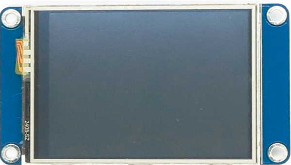
The Nextion 2.8 is a smart display module manufactured by Nextion, featuring a 2.8-inch resistive touchscreen interface. It is designed to simplify the development of Human-Machine Interfaces (HMI) by integrating a built-in microcontroller and a user-friendly design environment. The module communicates via UART (serial communication), making it compatible with a wide range of microcontrollers, including Arduino, Raspberry Pi, and other embedded systems.
Explore Projects Built with nextion 2.8

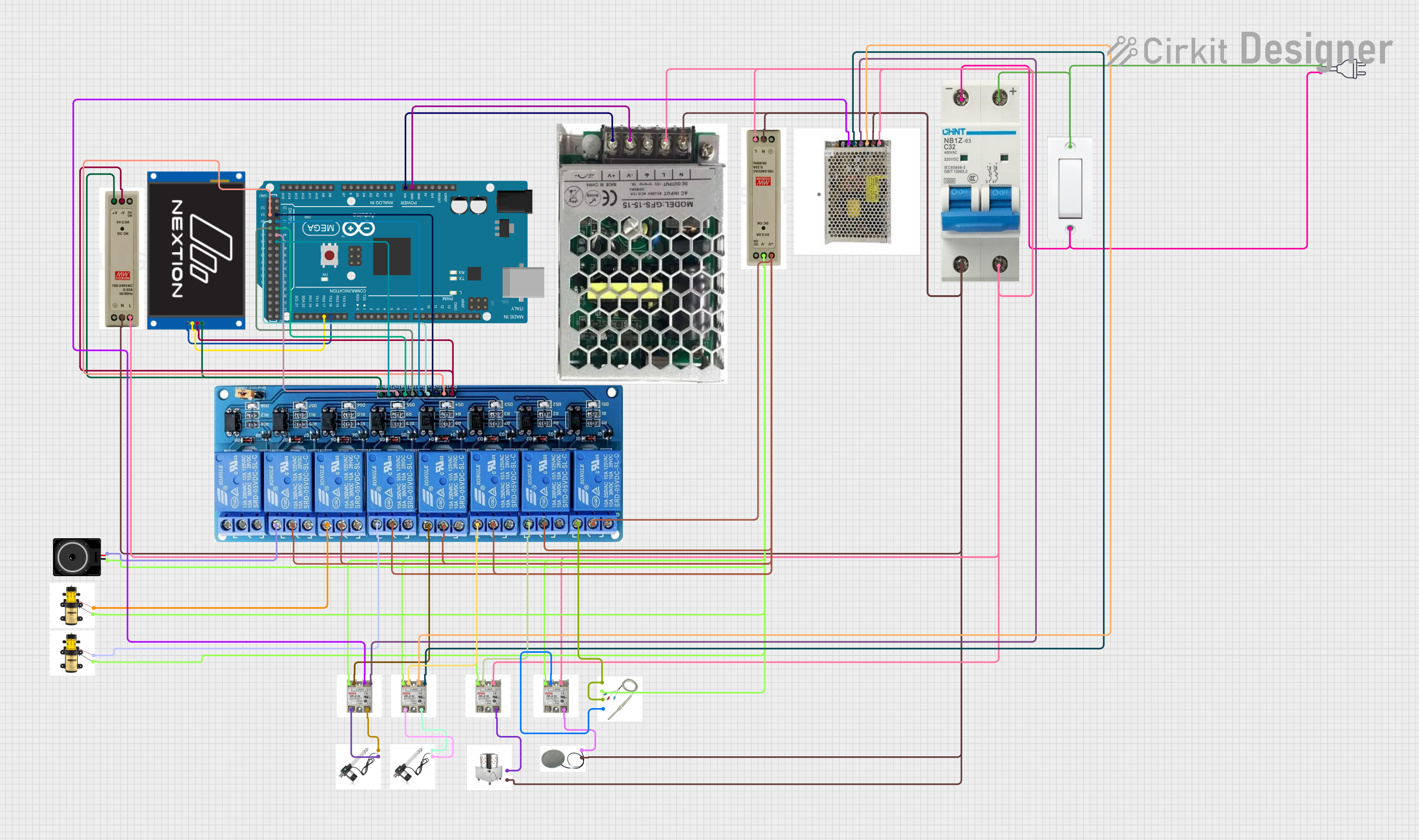
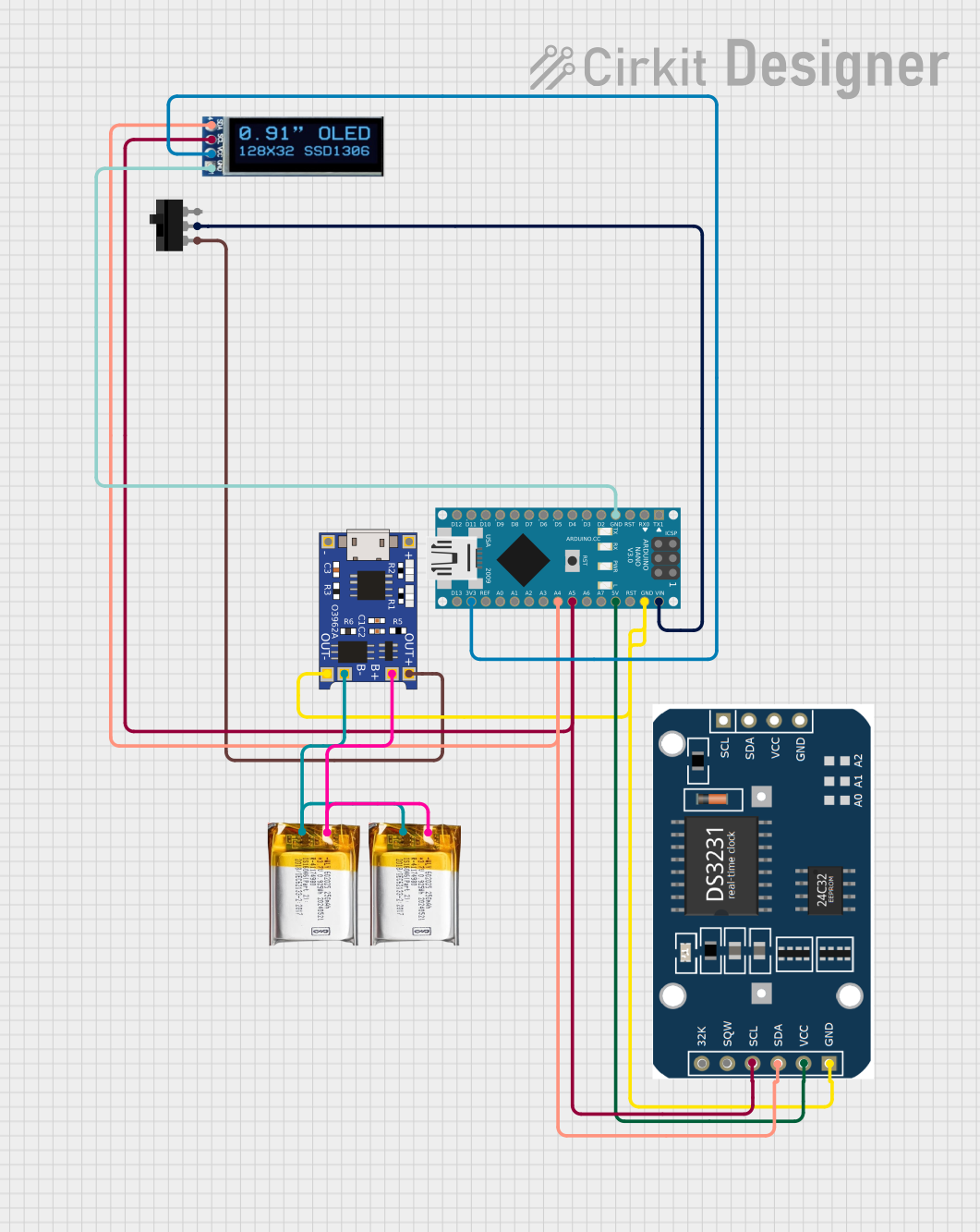
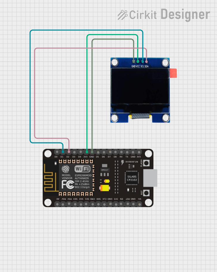
Explore Projects Built with nextion 2.8
Common Applications and Use Cases
- IoT devices and smart home automation
- Industrial control panels
- Medical devices with touch-based interfaces
- Educational and prototyping projects
- Consumer electronics with interactive displays
Technical Specifications
Below are the key technical details of the Nextion 2.8 smart display module:
| Specification | Details |
|---|---|
| Display Type | 2.8-inch TFT resistive touchscreen |
| Resolution | 320 x 240 pixels (QVGA) |
| Color Depth | 65K (16-bit RGB) |
| Communication Interface | UART (TTL, 9600 bps default) |
| Input Voltage | 4.75V to 7V |
| Power Consumption | 90mA (typical) |
| Operating Temperature | -20°C to 70°C |
| Storage Temperature | -30°C to 85°C |
| Flash Memory | 4MB |
| RAM | 3584 bytes |
| Dimensions | 85mm x 50mm x 5.1mm |
Pin Configuration and Descriptions
The Nextion 2.8 module has a 4-pin interface for power and communication:
| Pin | Name | Description |
|---|---|---|
| 1 | GND | Ground connection |
| 2 | VCC | Power supply (4.75V to 7V) |
| 3 | TX | Transmit data (output from Nextion to host device) |
| 4 | RX | Receive data (input to Nextion from host device) |
Usage Instructions
How to Use the Component in a Circuit
- Powering the Module: Connect the
VCCpin to a 5V power source and theGNDpin to the ground of your circuit. - Serial Communication: Connect the
TXpin of the Nextion module to the RX pin of your microcontroller, and theRXpin of the Nextion module to the TX pin of your microcontroller. - Programming the Display:
- Use the Nextion Editor software to design your user interface (UI). This software allows you to add buttons, sliders, text fields, and other UI elements.
- Compile and upload the UI design to the Nextion module via a microSD card or serial connection.
- Interfacing with a Microcontroller:
- Use UART communication to send and receive commands between the Nextion module and your microcontroller.
- Libraries such as the Nextion Arduino library can simplify communication.
Important Considerations and Best Practices
- Power Supply: Ensure a stable power supply to avoid display flickering or unexpected resets.
- Baud Rate: The default baud rate is 9600 bps. You can change it in the Nextion Editor if needed.
- Touch Calibration: The module is pre-calibrated, but you can recalibrate it using the Nextion Editor if required.
- Avoid Direct Connections to 3.3V Logic: If your microcontroller operates at 3.3V logic levels, use a level shifter for the TX and RX lines to ensure proper communication.
Example Code for Arduino UNO
Below is an example of how to interface the Nextion 2.8 with an Arduino UNO:
#include <Nextion.h>

// Define Nextion display object with serial communication
// Connect Nextion TX to Arduino pin 2 (RX) and RX to pin 3 (TX)
SoftwareSerial nextionSerial(2, 3); // RX, TX
Nextion myNextion(nextionSerial, 9600); // Initialize Nextion with 9600 baud rate

void setup() {
  nextionSerial.begin(9600); // Start serial communication with Nextion
  Serial.begin(9600);        // Start serial communication with PC for debugging

  // Send a command to clear the screen and display "Hello, World!"
  myNextion.init(); // Initialize the Nextion display
  myNextion.sendCommand("cls WHITE"); // Clear screen with white background
  myNextion.sendCommand("xstr 50,50,200,30,0,BLACK,WHITE,1,1,1,\"Hello, World!\"");
}

void loop() {
  // Example: Read touch events (if any)
  String touchData = myNextion.listen();
  if (touchData != "") {
    Serial.println("Touch Event: " + touchData); // Print touch data to Serial Monitor
  }
}
Troubleshooting and FAQs
Common Issues and Solutions
Display Not Powering On:
- Ensure the
VCCandGNDpins are properly connected. - Verify that the power supply provides sufficient voltage (4.75V to 7V).
- Ensure the
No Communication with Microcontroller:
- Check the TX and RX connections. Ensure they are not swapped.
- Verify that the baud rate in your code matches the baud rate of the Nextion module.
Touchscreen Not Responding:
- Ensure the display is not physically damaged.
- Recalibrate the touchscreen using the Nextion Editor.
UI Not Displaying Correctly:
- Confirm that the UI design was successfully uploaded to the module.
- Check the microSD card for errors if used for uploading.
FAQs
Q: Can I use the Nextion 2.8 with a 3.3V microcontroller?
A: Yes, but you must use a level shifter for the TX and RX lines to ensure proper communication.
Q: How do I reset the module to factory settings?
A: Use the Nextion Editor to upload a blank project or send the rest command via serial communication.
Q: Can I use the Nextion 2.8 for video playback?
A: No, the Nextion 2.8 does not support video playback. It is designed for static and interactive UI elements.
Q: What is the maximum size of the UI project I can upload?
A: The module has 4MB of flash memory for storing UI projects. Ensure your project size does not exceed this limit.