
How to Use XT90-BIG: Examples, Pinouts, and Specs
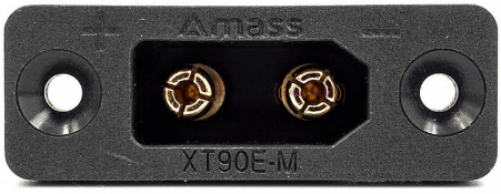
 Design with XT90-BIG in Cirkit Designer
Introduction
The XT90-BIG is a high-current connector designed for use in RC (radio-controlled) applications and other high-power setups. It is widely recognized for its robust design, reliability, and ability to handle high currents up to 90A. The XT90-BIG ensures secure connections with minimal voltage drop, making it ideal for demanding applications such as electric vehicles, drones, and high-performance battery packs.
Explore Projects Built with XT90-BIG
 Open Project in Cirkit Designer
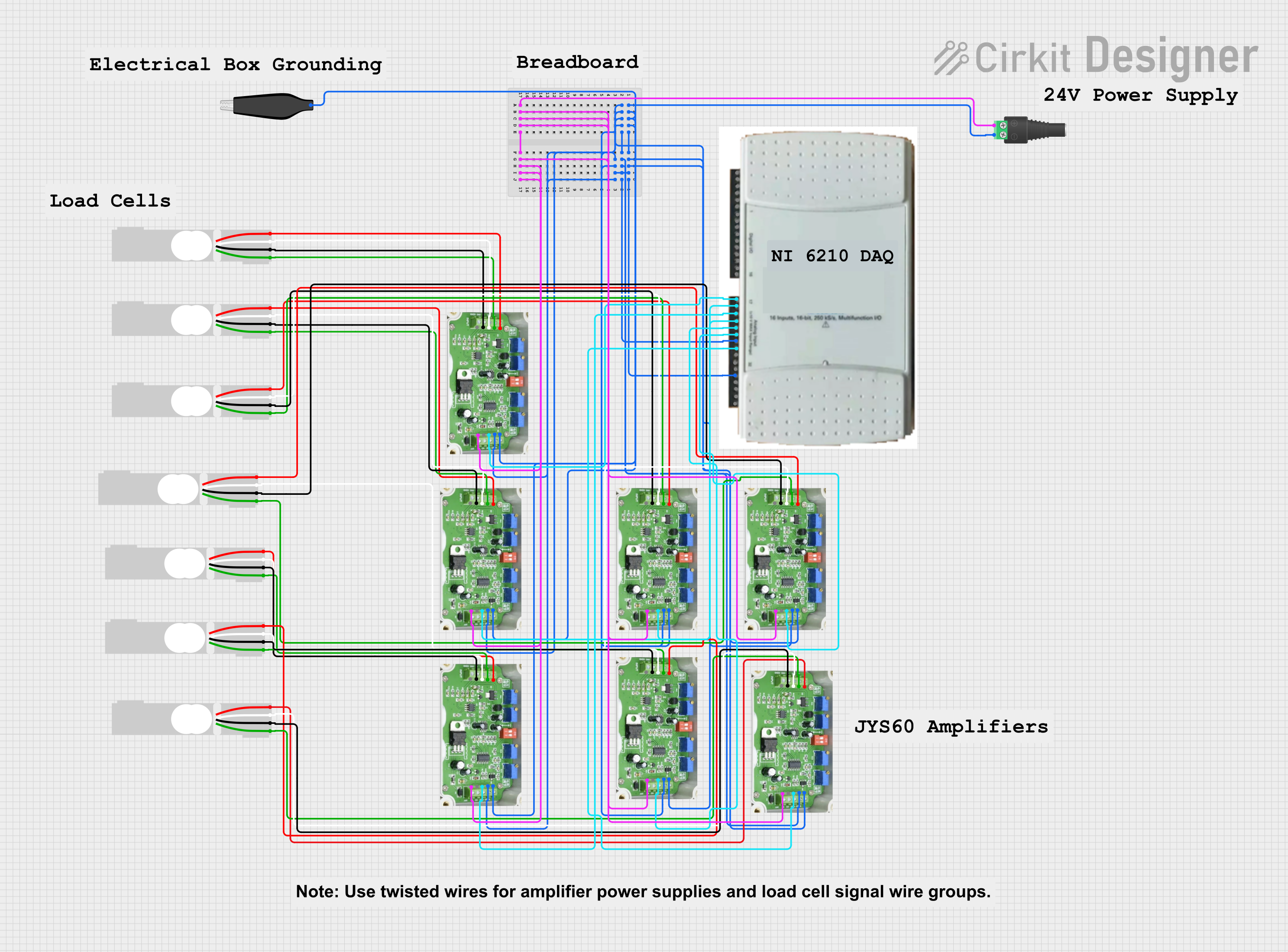 Open Project in Cirkit Designer
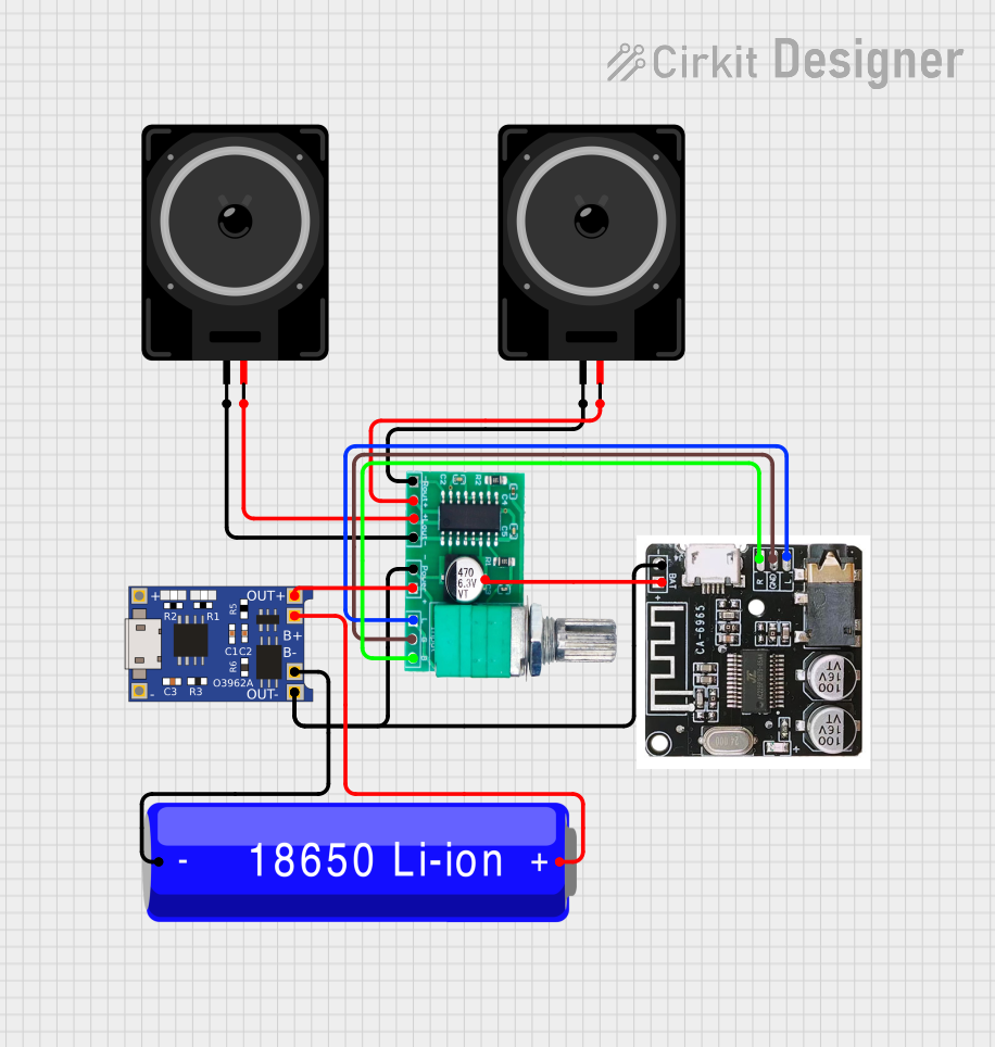 Open Project in Cirkit Designer
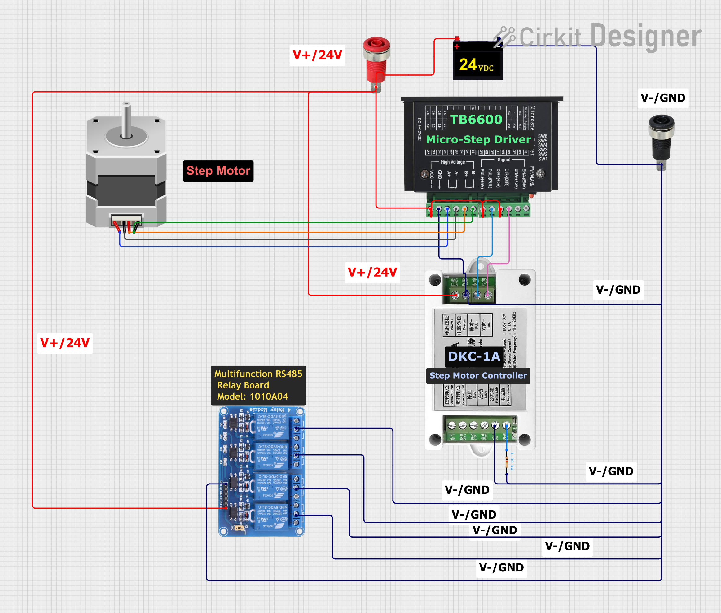 Open Project in Cirkit Designer
Explore Projects Built with XT90-BIG
Open Project in Cirkit DesignerOpen Project in Cirkit DesignerOpen Project in Cirkit DesignerOpen Project in Cirkit DesignerCommon Applications and Use Cases
- RC vehicles (cars, boats, planes, and drones)
- High-power battery packs for electric vehicles
- Solar power systems
- High-current DC power distribution
- Industrial equipment requiring secure, high-current connections
Technical Specifications
Key Technical Details
| Parameter | Value |
|---|---|
| Rated Current | 90A |
| Peak Current | 120A (for short durations) |
| Voltage Rating | Up to 500V DC |
| Contact Resistance | ≤ 0.85mΩ |
| Operating Temperature | -20°C to 120°C |
| Connector Material | Nylon (high-temperature resistant) |
| Contact Material | Gold-plated copper |
| Wire Gauge Support | 10-12 AWG |
Pin Configuration and Descriptions
The XT90-BIG connector consists of two main terminals: Positive (+) and Negative (-). These terminals are clearly marked on the connector housing to prevent reverse polarity connections.
| Pin Name | Description |
|---|---|
| Positive (+) | Connects to the positive terminal of the power source or load |
| Negative (-) | Connects to the negative terminal of the power source or load |
Usage Instructions
How to Use the XT90-BIG in a Circuit
- Prepare the Wires: Strip the insulation from the wires you intend to connect to the XT90-BIG. Ensure the wire gauge is between 10-12 AWG for optimal performance.
- Solder the Wires:
- Heat the soldering iron to an appropriate temperature (around 350°C).
- Tin the exposed wire ends and the XT90-BIG terminals with solder.
- Insert the tinned wire into the terminal and apply heat until the solder flows and creates a secure connection.
- Assemble the Connector: Once the solder joints cool, slide the connector housing over the terminals to complete the assembly.
- Connect to the Circuit: Plug the XT90-BIG connectors together, ensuring the positive and negative terminals align correctly.
Important Considerations and Best Practices
- Polarity Check: Always double-check the polarity markings on the connector to avoid reverse polarity connections, which can damage your circuit.
- Soldering Precautions: Avoid overheating the terminals during soldering, as excessive heat can deform the nylon housing.
- Secure Connections: Ensure the connectors are fully mated to prevent loose connections, which can lead to arcing or increased resistance.
- Wire Gauge: Use the recommended wire gauge (10-12 AWG) to handle the rated current without overheating.
- Heat Shrink Tubing: Use heat shrink tubing over the soldered connections for added insulation and strain relief.
Example: Connecting XT90-BIG to an Arduino-Powered Circuit
While the XT90-BIG is not directly connected to an Arduino, it can be used to supply power to an Arduino-based system. Below is an example of how to use the XT90-BIG in a power distribution setup for an Arduino UNO:
// Example Arduino code for a power distribution system
// This code assumes the XT90-BIG is used to connect a battery to a power
// distribution board, which powers the Arduino UNO and other components.

void setup() {
  // Initialize the Arduino system
  Serial.begin(9600); // Start serial communication at 9600 baud
  pinMode(13, OUTPUT); // Set pin 13 as an output (e.g., for an LED)
}

void loop() {
  // Example: Blink an LED to indicate the system is powered
  digitalWrite(13, HIGH); // Turn the LED on
  delay(1000);            // Wait for 1 second
  digitalWrite(13, LOW);  // Turn the LED off
  delay(1000);            // Wait for 1 second
}
Troubleshooting and FAQs
Common Issues and Solutions
| Issue | Possible Cause | Solution |
|---|---|---|
| Connector gets hot during use | High resistance due to poor soldering | Re-solder the connections to ensure a secure joint |
| Loose connection | Connector not fully mated | Ensure the connectors are fully plugged in |
| Reverse polarity connection | Incorrect wiring | Double-check the polarity markings before connecting |
| Deformed housing | Excessive heat during soldering | Use a temperature-controlled soldering iron and avoid prolonged heating |
FAQs
Q: Can the XT90-BIG handle currents above 90A?
A: The XT90-BIG can handle peak currents of up to 120A for short durations. However, for continuous operation, it is recommended to stay within the 90A rating to avoid overheating.
Q: Is the XT90-BIG waterproof?
A: No, the XT90-BIG is not waterproof. If you need to use it in wet environments, consider additional waterproofing measures such as heat shrink tubing with adhesive or a waterproof enclosure.
Q: Can I use smaller gauge wires with the XT90-BIG?
A: It is not recommended to use wires smaller than 12 AWG, as they may not handle the rated current and could lead to overheating or voltage drops.
Q: How do I disconnect the XT90-BIG connectors?
A: Firmly grip both connectors and pull them apart. Avoid pulling on the wires to prevent damage.
By following this documentation, you can effectively use the XT90-BIG connector in your high-power applications with confidence and reliability.