How to Use 74HC595: Examples, Pinouts, and Specs
74HC595 Shift Register Documentation
1. Introduction
The 74HC595 is an 8-bit serial-in, parallel-out shift register with a storage register and tri-state outputs. It is widely used in electronics to expand the number of output pins available on a microcontroller, such as an Arduino. By using a serial data input, the 74HC595 allows you to control up to 8 output pins with just 3 control pins from the microcontroller. Additionally, multiple 74HC595 chips can be cascaded to control even more outputs.
Common Applications
- Driving LED arrays or 7-segment displays
- Controlling relays or other digital outputs
- Expanding GPIO pins on microcontrollers
- Multiplexing and demultiplexing signals
- Building digital counters or shift registers
2. Technical Specifications
The following table outlines the key technical details of the 74HC595:
| Parameter | Value |
|---|---|
| Supply Voltage (Vcc) | 2V to 6V |
| Input Voltage (VI) | 0V to Vcc |
| Output Current (IO) | ±6 mA per pin |
| Maximum Clock Frequency | 25 MHz (at 4.5V) |
| Operating Temperature | -40°C to +125°C |
| Propagation Delay | ~20 ns (at 5V) |
| Package Types | DIP-16, SOIC-16, TSSOP-16 |
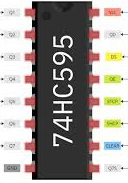
Pin Configuration and Descriptions
The 74HC595 has 16 pins, as described in the table below:
| Pin Number | Pin Name | Description |
|---|---|---|
| 1 | Q1 | Parallel output pin 1 |
| 2 | Q2 | Parallel output pin 2 |
| 3 | Q3 | Parallel output pin 3 |
| 4 | Q4 | Parallel output pin 4 |
| 5 | Q5 | Parallel output pin 5 |
| 6 | Q6 | Parallel output pin 6 |
| 7 | Q7 | Parallel output pin 7 |
| 8 | GND | Ground (0V) |
| 9 | Q7' | Serial data output for cascading additional 74HC595 chips |
| 10 | MR | Master Reset (active LOW) - Clears all outputs |
| 11 | SH_CP | Shift Register Clock Input - Shifts data into the register on rising edge |
| 12 | ST_CP | Storage Register Clock Input (Latch) - Transfers data to output on rising edge |
| 13 | OE | Output Enable (active LOW) - Enables/disables outputs |
| 14 | DS | Serial Data Input |
| 15 | Q0 | Parallel output pin 0 |
| 16 | Vcc | Positive supply voltage |
3. Usage Instructions
Connecting the 74HC595 to a Microcontroller
To use the 74HC595, connect it to your microcontroller as follows:
- Power Supply: Connect
Vccto the microcontroller's 5V pin andGNDto ground. - Control Pins:
- Connect
DS(Pin 14) to the microcontroller's data pin (e.g., ArduinoD11). - Connect
SH_CP(Pin 11) to the microcontroller's clock pin (e.g., ArduinoD12). - Connect
ST_CP(Pin 12) to the microcontroller's latch pin (e.g., ArduinoD8).
- Connect
- Output Enable: Connect
OE(Pin 13) to ground to enable the outputs. - Master Reset: Connect
MR(Pin 10) to Vcc to disable the reset function.
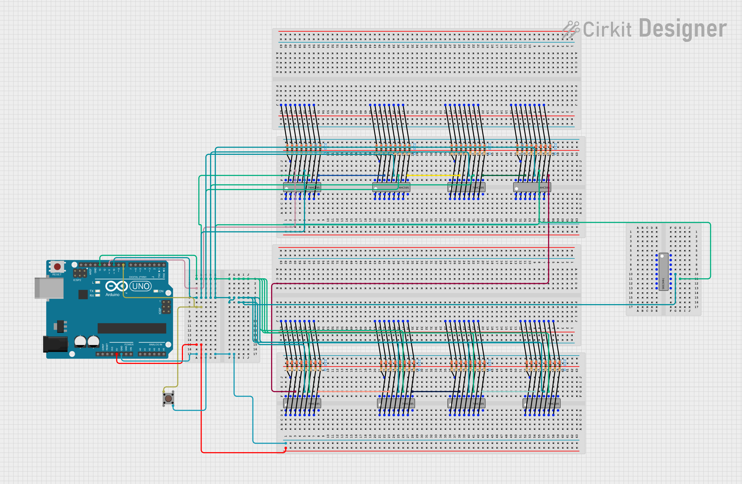
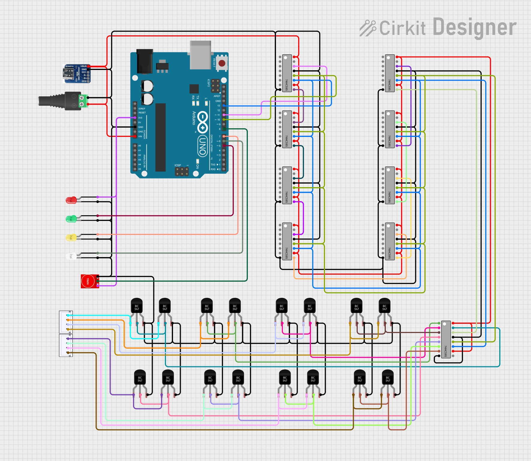
Cascading Multiple 74HC595 Chips
To control more than 8 outputs, you can cascade multiple 74HC595 chips:
- Connect the
Q7'(Pin 9) of the first chip to theDS(Pin 14) of the second chip. - Share the
SH_CP,ST_CP, andOEpins across all chips.
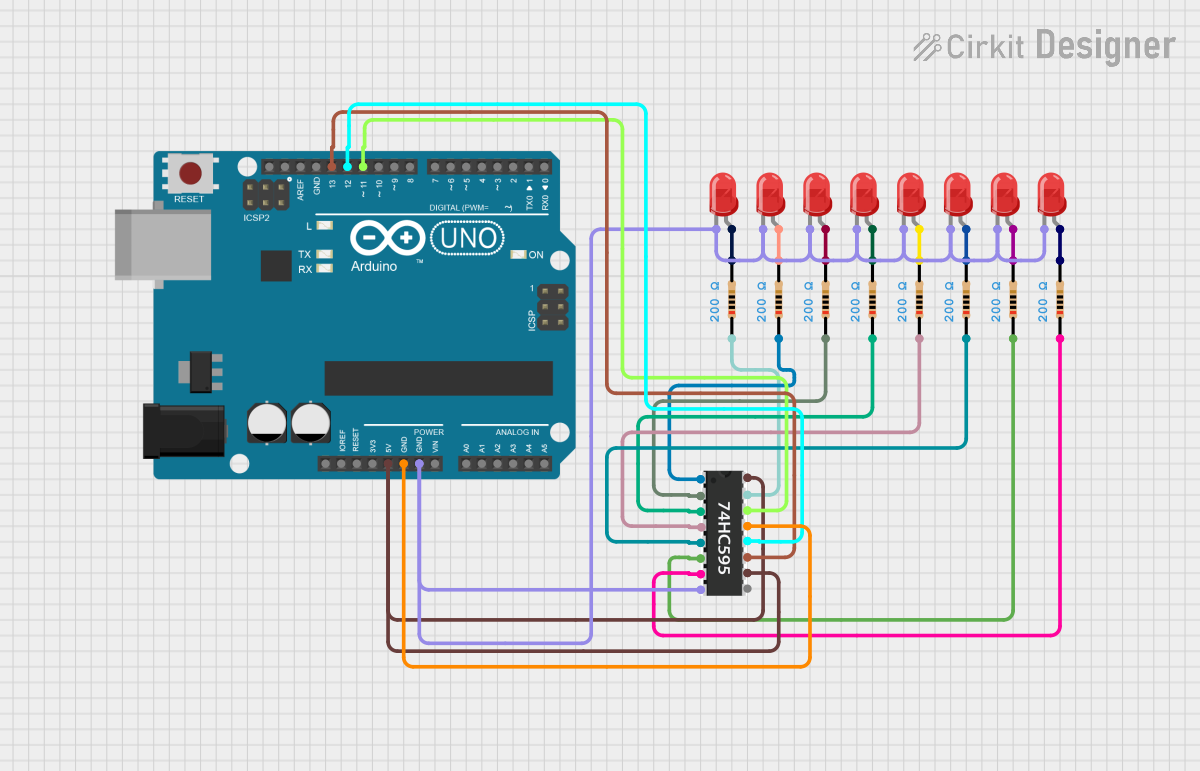
Example Circuit
Below is an example of connecting a single 74HC595 to an Arduino UNO to control 8 LEDs:
74HC595 Pin 14 (DS)  -> Arduino Pin 11
74HC595 Pin 11 (SH_CP) -> Arduino Pin 12
74HC595 Pin 12 (ST_CP) -> Arduino Pin 8
74HC595 Pin 13 (OE) -> GND
74HC595 Pin 10 (MR) -> Vcc
74HC595 Pin 16 (Vcc) -> Arduino 5V
74HC595 Pin 8 (GND) -> Arduino GND
74HC595 Pins Q0-Q7 -> LEDs (with current-limiting resistors)
4. Arduino Code Example
Here is an example Arduino sketch to control 8 LEDs using the 74HC595:
// Define 74HC595 control pins
const int dataPin = 11;  // DS (Serial Data Input)
const int clockPin = 12; // SH_CP (Shift Register Clock)
const int latchPin = 8;  // ST_CP (Storage Register Clock)

// Function to send data to the 74HC595
void shiftOutData(byte data) {
  digitalWrite(latchPin, LOW);  // Disable latch to update data
  shiftOut(dataPin, clockPin, MSBFIRST, data); // Send data (MSB first)
  digitalWrite(latchPin, HIGH); // Enable latch to output data
}

void setup() {
  // Set control pins as outputs
  pinMode(dataPin, OUTPUT);
  pinMode(clockPin, OUTPUT);
  pinMode(latchPin, OUTPUT);
}

void loop() {
  // Turn on LEDs one by one
  for (byte i = 0; i < 8; i++) {
    shiftOutData(1 << i); // Shift a single HIGH bit through the register
    delay(200);           // Wait 200ms
  }

  // Turn off LEDs one by one
  for (byte i = 0; i < 8; i++) {
    shiftOutData(~(1 << i)); // Shift a single LOW bit through the register
    delay(200);              // Wait 200ms
  }
}
5. Troubleshooting and FAQs
Common Issues and Solutions
| Issue | Possible Cause | Solution |
|---|---|---|
| LEDs not lighting up | Incorrect wiring or loose connections | Double-check all connections and ensure proper wiring. |
| Outputs not updating | Latch pin (ST_CP) not toggled correctly |
Ensure the latch pin is toggled HIGH after sending data. |
| Cascaded chips not working | Incorrect connection of Q7' to DS |
Verify the Q7' of the first chip is connected to the DS of the next chip. |
| Flickering LEDs | Clock signal is noisy or too fast | Use a lower clock frequency or add decoupling capacitors near the chip. |
| Outputs always HIGH or LOW | OE or MR pins not properly connected |
Ensure OE is grounded and MR is connected to Vcc. |
FAQs
Can I use the 74HC595 with 3.3V microcontrollers?
- Yes, the 74HC595 operates at voltages as low as 2V. Ensure the output current is within limits.
How many 74HC595 chips can I cascade?
- Theoretically, you can cascade as many as you want, but practical limits depend on signal integrity and timing.
Do I need resistors for LEDs connected to the 74HC595?
- Yes, always use current-limiting resistors to protect the LEDs and the 74HC595 outputs.
What is the purpose of the
OEpin?- The
OEpin enables or disables the outputs. When HIGH, all outputs are in a high-impedance state.
- The
This documentation provides a comprehensive guide to using the 74HC595 shift register. Whether you're a beginner or an experienced user, the 74HC595 is a versatile and essential component for expanding your microcontroller's output capabilities.
Explore Projects Built with 74HC595

Explore Projects Built with 74HC595