
How to Use 48V to 12v: Examples, Pinouts, and Specs
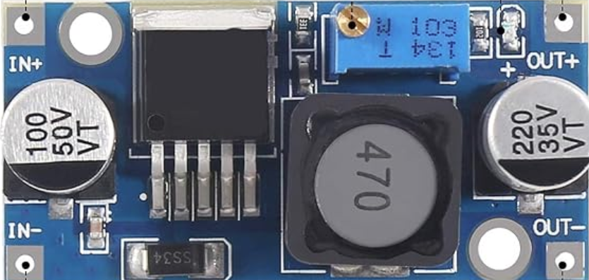
 Design with 48V to 12v in Cirkit Designer
Introduction
The 48V to 12V voltage converter is an electronic component designed to step down a 48-volt input to a stable 12-volt output. This component is widely used in power supply applications where devices require a lower voltage for operation. It is commonly found in automotive systems, industrial equipment, and renewable energy setups such as solar power systems. The converter ensures efficient power delivery while protecting connected devices from overvoltage.
Explore Projects Built with 48V to 12v
 Open Project in Cirkit Designer
 Open Project in Cirkit Designer
 Open Project in Cirkit Designer
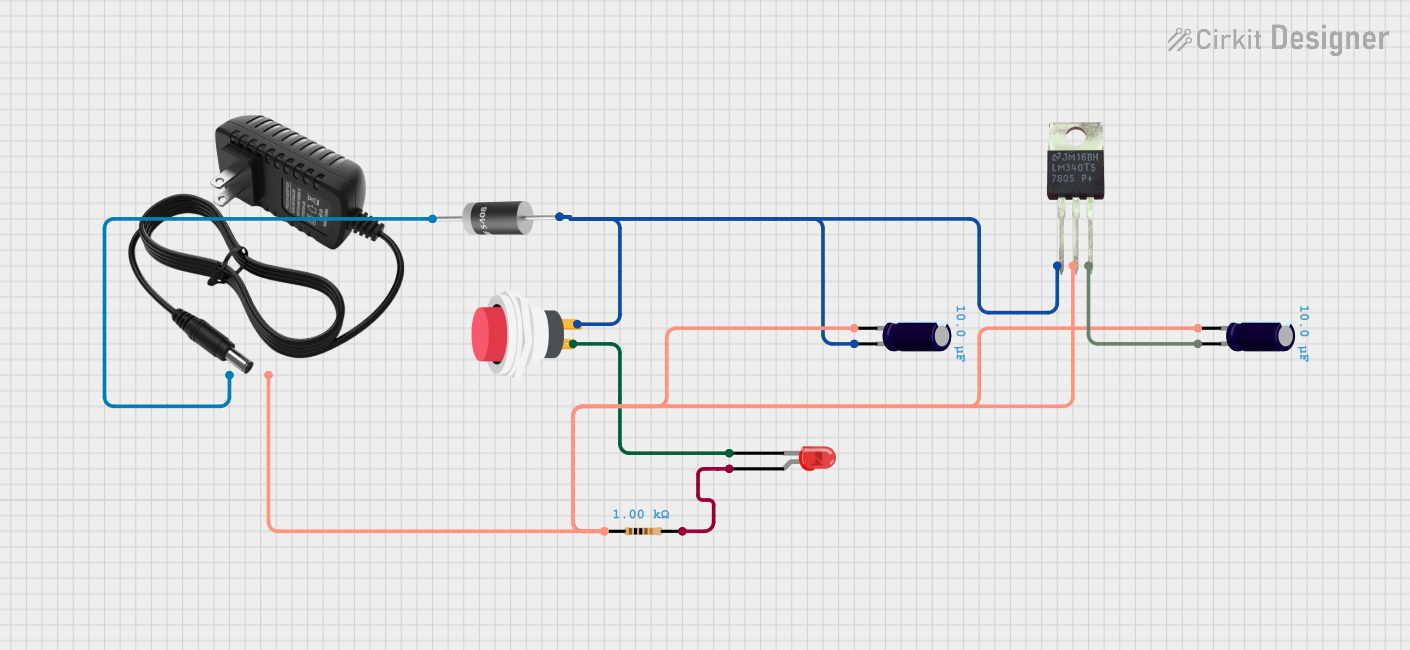 Open Project in Cirkit Designer
Explore Projects Built with 48V to 12v
Open Project in Cirkit DesignerOpen Project in Cirkit DesignerOpen Project in Cirkit DesignerOpen Project in Cirkit DesignerTechnical Specifications
Below are the key technical details of the 48V to 12V voltage converter:
| Parameter | Value |
|---|---|
| Input Voltage Range | 36V - 60V |
| Output Voltage | 12V ± 0.5V |
| Maximum Output Current | 10A |
| Output Power | 120W |
| Efficiency | Up to 95% |
| Operating Temperature | -40°C to +85°C |
| Protection Features | Overvoltage, Overcurrent, Overheat |
Pin Configuration and Descriptions
The 48V to 12V voltage converter typically has four connection terminals. Below is the pin configuration:
| Pin | Label | Description |
|---|---|---|
| 1 | VIN+ | Positive input terminal for 48V power supply |
| 2 | VIN- | Negative input terminal (ground) for 48V power supply |
| 3 | VOUT+ | Positive output terminal for 12V power supply |
| 4 | VOUT- | Negative output terminal (ground) for 12V power supply |
Usage Instructions
How to Use the Component in a Circuit
- Connect the Input Voltage:
- Attach the VIN+ terminal to the positive terminal of the 48V power source.
- Connect the VIN- terminal to the ground of the 48V power source.
- Connect the Output Voltage:
- Attach the VOUT+ terminal to the positive terminal of the 12V load.
- Connect the VOUT- terminal to the ground of the 12V load.
- Power On:
- Ensure all connections are secure and power on the 48V source. The converter will step down the voltage to 12V automatically.
Important Considerations and Best Practices
- Input Voltage Range: Ensure the input voltage is within the specified range (36V - 60V). Exceeding this range may damage the converter.
- Heat Dissipation: If the converter operates at high currents, ensure proper ventilation or use a heatsink to prevent overheating.
- Load Compatibility: Verify that the connected load does not exceed the maximum output current (10A).
- Polarity: Double-check the polarity of all connections to avoid damage to the converter or connected devices.
Example: Using the Converter with an Arduino UNO
The 48V to 12V converter can be used to power an Arduino UNO by stepping down the voltage to 12V and then connecting it to the Arduino's VIN pin. Below is an example circuit and code:
Circuit Setup
- Connect the converter's VIN+ and VIN- terminals to a 48V power source.
- Connect the converter's VOUT+ to the Arduino's VIN pin.
- Connect the converter's VOUT- to the Arduino's GND pin.
Example Code
// Example code for Arduino UNO powered by a 48V to 12V converter
// This code blinks an LED connected to pin 13

void setup() {
  pinMode(13, OUTPUT); // Set pin 13 as an output for the LED
}

void loop() {
  digitalWrite(13, HIGH); // Turn the LED on
  delay(1000);            // Wait for 1 second
  digitalWrite(13, LOW);  // Turn the LED off
  delay(1000);            // Wait for 1 second
}
Troubleshooting and FAQs
Common Issues and Solutions
No Output Voltage:
- Cause: Incorrect wiring or loose connections.
- Solution: Double-check all connections and ensure proper polarity.
Overheating:
- Cause: Excessive load or poor ventilation.
- Solution: Reduce the load or improve airflow around the converter.
Output Voltage Fluctuations:
- Cause: Input voltage instability or load exceeding the rated capacity.
- Solution: Use a stable power source and ensure the load is within the specified limits.
Converter Not Powering On:
- Cause: Input voltage is outside the specified range.
- Solution: Verify the input voltage is between 36V and 60V.
FAQs
Q: Can I use this converter to power a 5V device?
A: No, this converter outputs a fixed 12V. To power a 5V device, you will need an additional step-down converter (e.g., a 12V to 5V regulator).
Q: Is the converter waterproof?
A: Most converters are not waterproof unless explicitly stated. Use appropriate enclosures for outdoor or wet environments.
Q: Can I connect multiple converters in parallel for higher current?
A: It is not recommended unless the converters are specifically designed for parallel operation, as this may cause uneven load sharing.
Q: What happens if I reverse the input polarity?
A: Many converters include reverse polarity protection, but it is best to avoid this scenario as it may still damage the device.
By following this documentation, you can safely and effectively use the 48V to 12V voltage converter in your projects.