How to Use JST SM 3: Examples, Pinouts, and Specs
Introduction
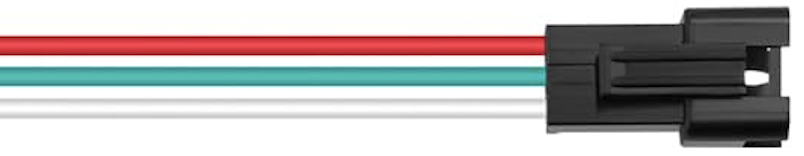
The JST SM 3 is a compact, reliable 3-pin connector manufactured by JST. It is widely used in electronic circuits for connecting wires securely, thanks to its robust locking mechanism. This connector is designed to provide a stable and durable connection, making it ideal for applications where vibration or movement might otherwise cause disconnections.
Explore Projects Built with JST SM 3
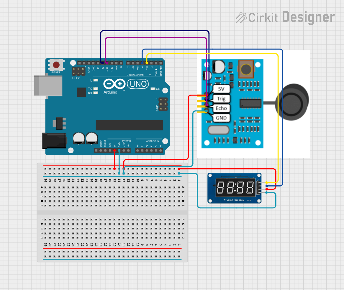
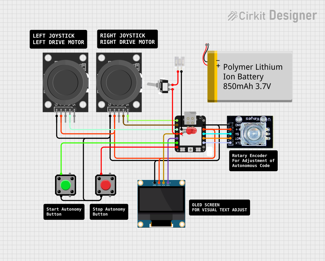
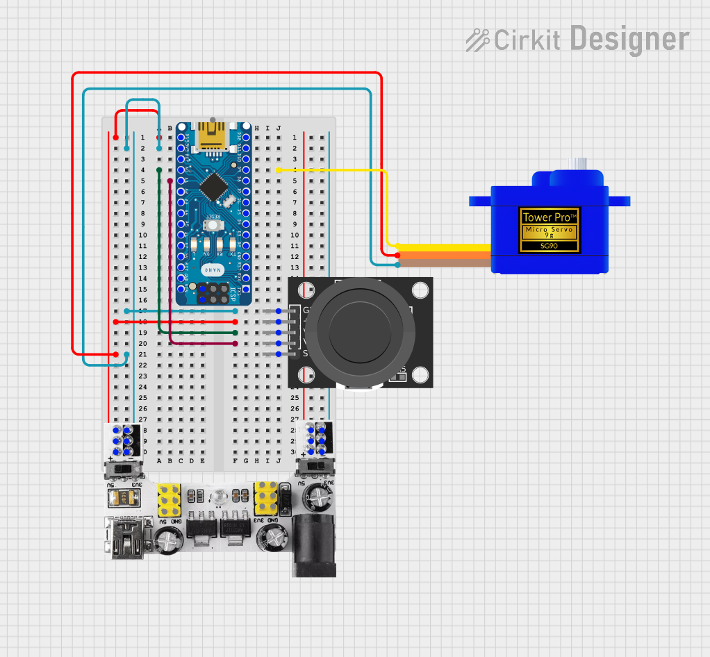

Explore Projects Built with JST SM 3
Common Applications and Use Cases
- LED strip connections
- RC vehicles and drones
- Battery packs and power distribution
- Small electronic devices and appliances
- Robotics and prototyping projects
Technical Specifications
The JST SM 3 connector is designed for low-voltage and low-current applications. Below are its key technical details:
| Parameter | Specification |
|---|---|
| Manufacturer | JST |
| Part ID | SM |
| Number of Pins | 3 |
| Current Rating | 3A (maximum) |
| Voltage Rating | 250V AC/DC (maximum) |
| Wire Gauge Support | 22-28 AWG |
| Operating Temperature | -25°C to +85°C |
| Contact Resistance | ≤ 20 mΩ |
| Insulation Resistance | ≥ 1000 MΩ |
| Connector Type | Male and Female (locking mechanism) |
| Material | Housing: Nylon, Contacts: Tin-plated |
Pin Configuration and Descriptions
The JST SM 3 connector consists of three pins, typically used for power and signal connections. Below is the pinout description:
| Pin Number | Description | Common Use |
|---|---|---|
| 1 | VCC (Power Supply) | Positive voltage input |
| 2 | GND (Ground) | Ground connection |
| 3 | Signal/Data | Signal or data line |
Usage Instructions
How to Use the JST SM 3 Connector in a Circuit
- Prepare the Wires: Strip the insulation from the wires you intend to connect, leaving about 5-7 mm of exposed conductor.
- Crimp the Contacts: Use a crimping tool to attach the metal contacts to the exposed wire ends. Ensure a secure crimp for reliable connections.
- Insert Contacts into Housing: Push the crimped contacts into the connector housing until they click into place. Ensure the locking mechanism is engaged.
- Connect Male and Female Parts: Align the male and female connectors and push them together until the locking mechanism clicks, ensuring a secure connection.
Important Considerations and Best Practices
- Wire Gauge: Use wires within the supported range (22-28 AWG) to ensure proper crimping and connection.
- Crimping Tool: Use a compatible crimping tool for JST SM connectors to avoid damaging the contacts.
- Polarity: Double-check the pin configuration to ensure correct polarity and avoid damage to your circuit.
- Secure Connections: Ensure the locking mechanism is fully engaged to prevent accidental disconnections, especially in applications with vibration or movement.
Example: Connecting to an Arduino UNO
The JST SM 3 connector can be used to connect an external device, such as an LED strip, to an Arduino UNO. Below is an example of how to connect and control an LED strip using the JST SM 3 connector:
Circuit Diagram
- Pin 1 (VCC): Connect to the 5V pin on the Arduino.
- Pin 2 (GND): Connect to the GND pin on the Arduino.
- Pin 3 (Signal): Connect to a PWM-capable pin (e.g., Pin 9) on the Arduino.
Arduino Code
// Example code to control an LED strip using a JST SM 3 connector
// Connect the signal pin of the JST SM 3 to Pin 9 on the Arduino

const int ledPin = 9; // PWM pin connected to the signal pin of the JST SM 3

void setup() {
  pinMode(ledPin, OUTPUT); // Set the LED pin as an output
}

void loop() {
  analogWrite(ledPin, 128); // Set LED brightness to 50% (128 out of 255)
  delay(1000); // Wait for 1 second
  analogWrite(ledPin, 255); // Set LED brightness to 100% (255 out of 255)
  delay(1000); // Wait for 1 second
}
Troubleshooting and FAQs
Common Issues and Solutions
Loose Connections:
- Issue: The connector feels loose or disconnects easily.
- Solution: Ensure the contacts are fully inserted into the housing and the locking mechanism is engaged.
Intermittent Signal:
- Issue: The signal or power connection is unstable.
- Solution: Check the crimped contacts for proper attachment to the wires. Re-crimp if necessary.
Overheating:
- Issue: The connector becomes warm during operation.
- Solution: Ensure the current does not exceed the 3A rating. Use thicker wires if necessary.
Incorrect Polarity:
- Issue: The connected device does not function or is damaged.
- Solution: Verify the pin configuration and ensure correct polarity before connecting.
FAQs
Q1: Can the JST SM 3 connector handle high-current applications?
A1: No, the JST SM 3 is rated for a maximum current of 3A. For higher currents, consider using connectors with higher current ratings.
Q2: Is the JST SM 3 connector waterproof?
A2: No, the standard JST SM 3 connector is not waterproof. For outdoor or moisture-prone applications, additional sealing or a waterproof connector is recommended.
Q3: Can I reuse the JST SM 3 connector?
A3: Yes, the connector can be reused, but the crimped contacts may need to be replaced if they are damaged or deformed during removal.
Q4: What crimping tool should I use for the JST SM 3?
A4: Use a crimping tool specifically designed for JST SM connectors to ensure proper crimping and avoid damaging the contacts.