How to Use PLC OMRON: Examples, Pinouts, and Specs

Introduction
The OMRON CP1L is a compact and versatile Programmable Logic Controller (PLC) designed for automating industrial processes. It offers robust programming capabilities, real-time control, and extensive input/output (I/O) options, making it suitable for a wide range of applications. The CP1L is ideal for small to medium-sized automation tasks, providing high performance in a compact form factor.
Explore Projects Built with PLC OMRON

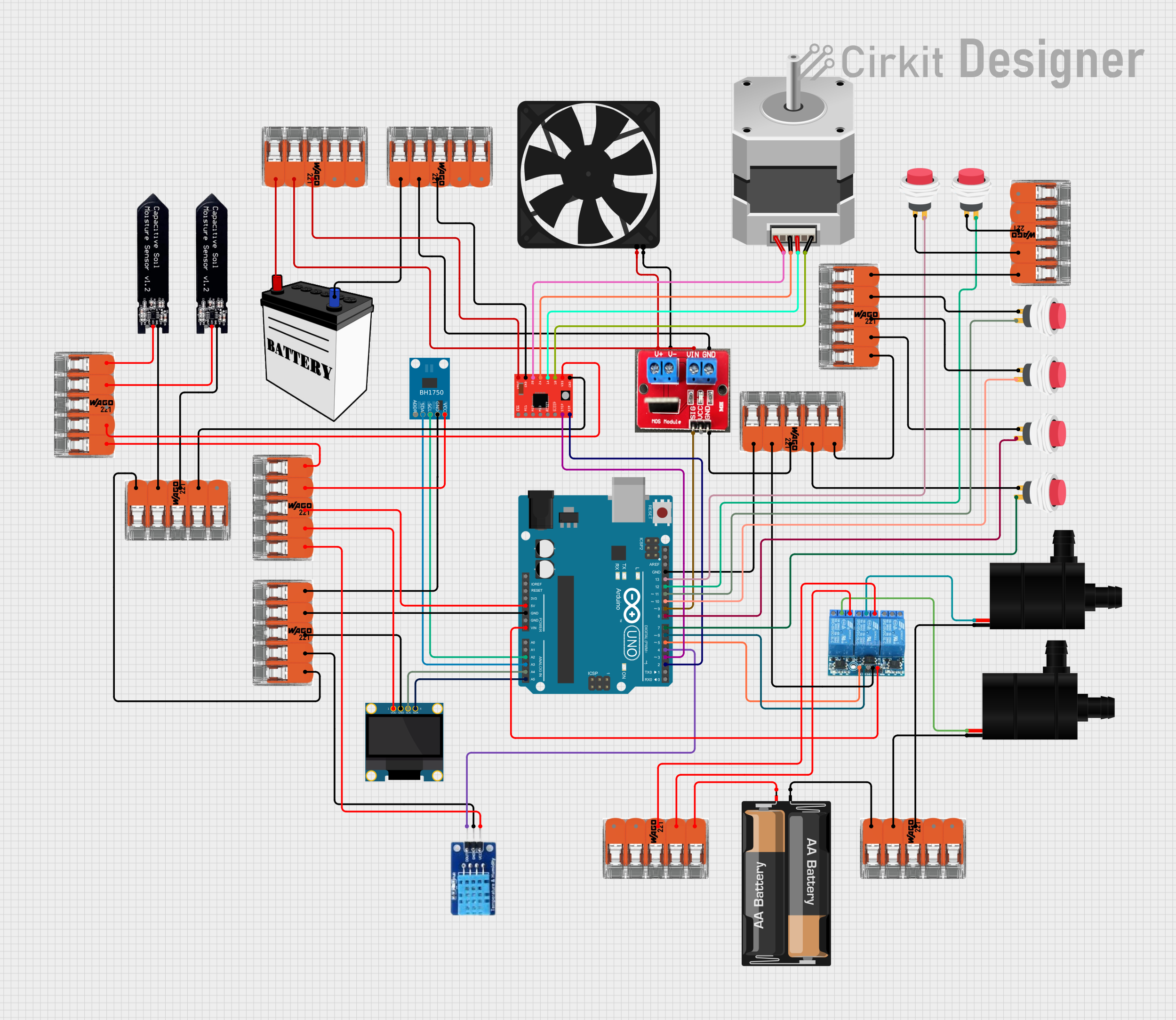
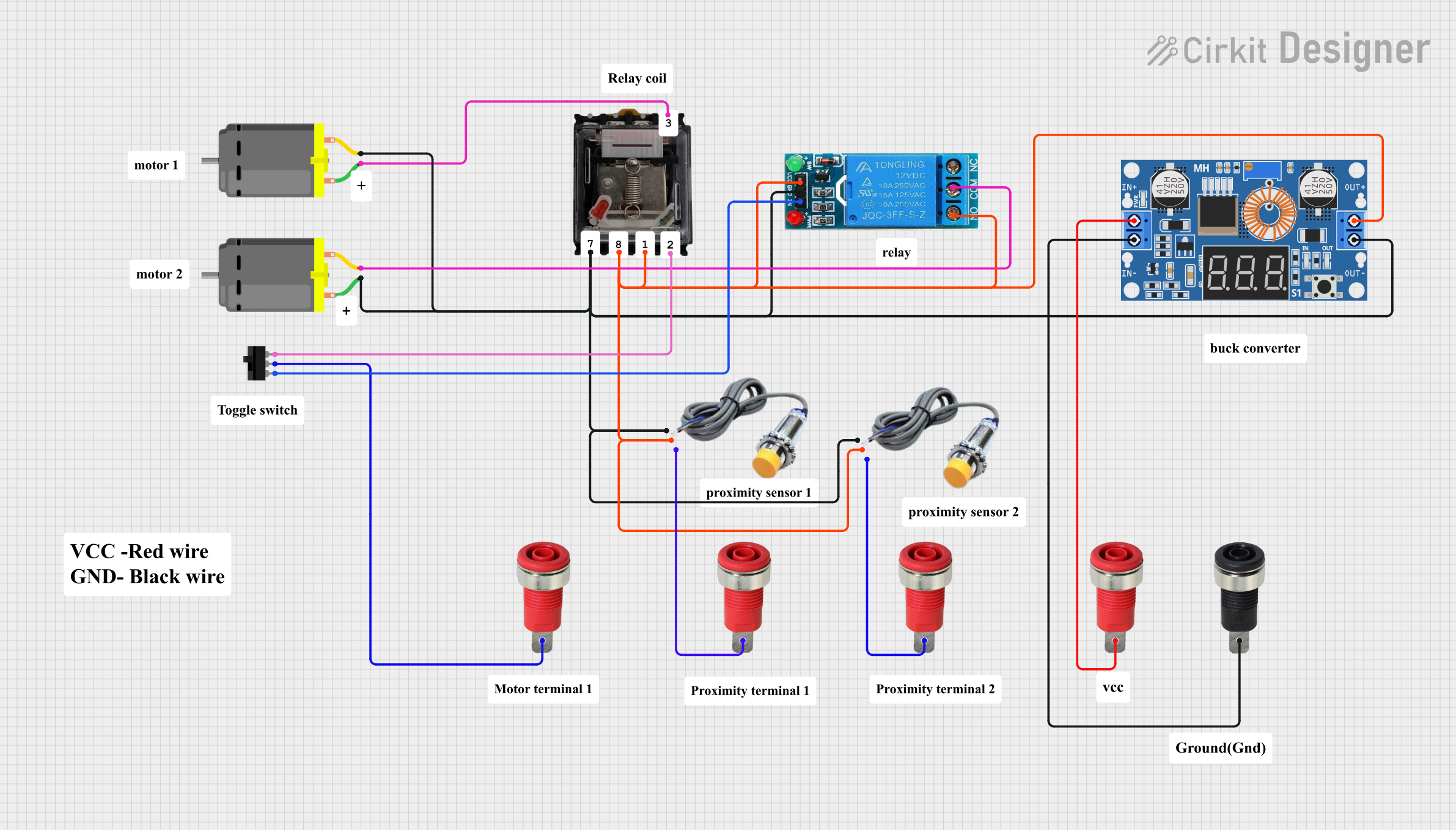
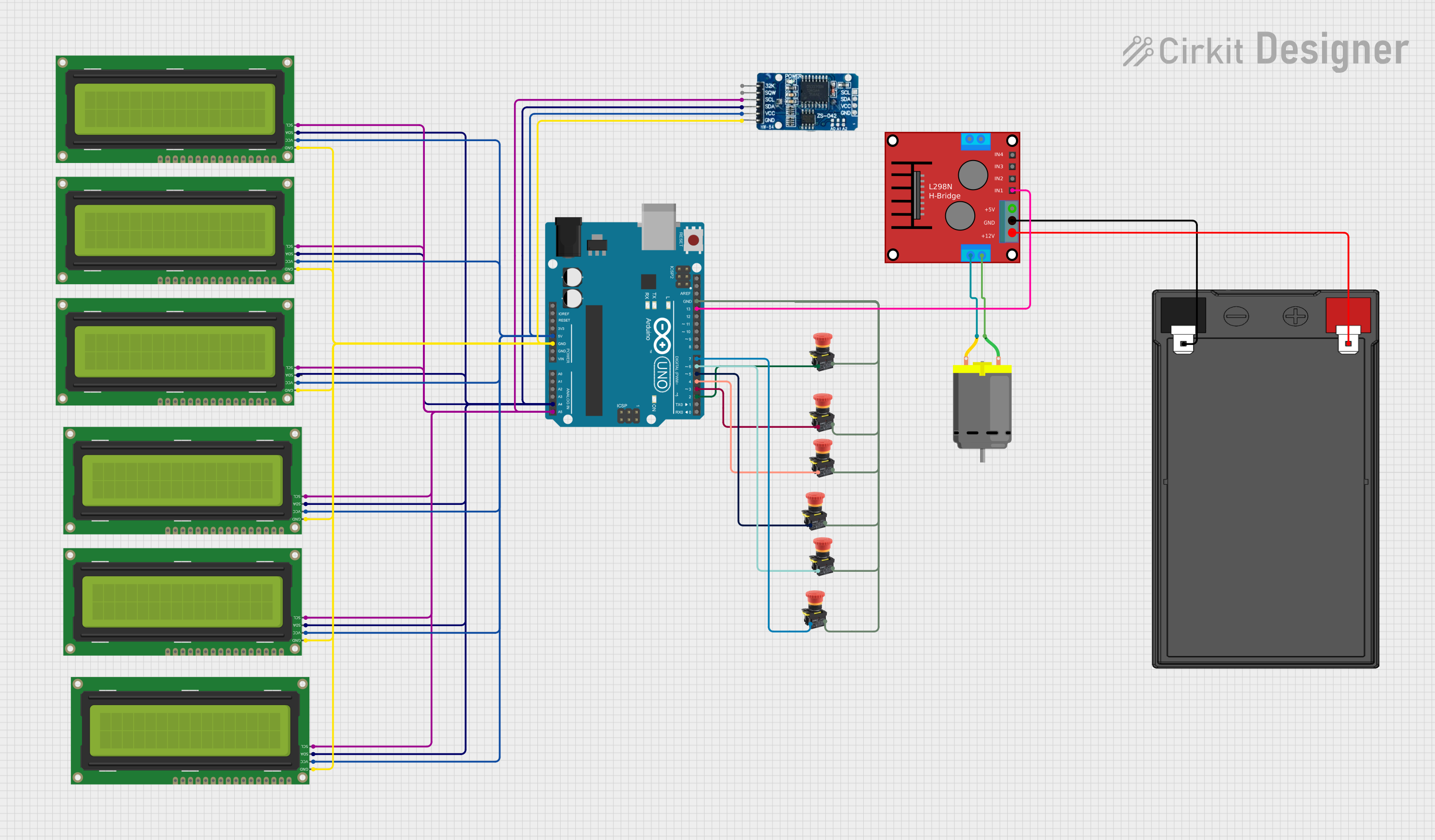
Explore Projects Built with PLC OMRON
Common Applications and Use Cases
- Industrial automation and process control
- Conveyor belt systems
- Packaging machinery
- HVAC systems
- Automated assembly lines
- Monitoring and controlling sensors and actuators
Technical Specifications
The OMRON CP1L PLC is available in various models with different I/O configurations. Below are the key technical specifications:
General Specifications
| Parameter | Value |
|---|---|
| Manufacturer | OMRON |
| Part Number | CP1L |
| Power Supply Voltage | 24 VDC or 100-240 VAC (model-dependent) |
| Program Capacity | 5 ksteps |
| Data Memory | 10 kwords |
| Communication Ports | USB, RS-232C, RS-485, Ethernet (optional) |
| Operating Temperature | 0°C to 55°C |
| Storage Temperature | -20°C to 75°C |
| Dimensions | Varies by model (e.g., 90x85x70 mm) |
I/O Specifications
| Model Variant | Digital Inputs | Digital Outputs | Analog Inputs | Analog Outputs |
|---|---|---|---|---|
| CP1L-L10 | 6 | 4 | 0 | 0 |
| CP1L-L14 | 8 | 6 | 0 | 0 |
| CP1L-L20 | 12 | 8 | 0 | 0 |
| CP1L-L30 | 18 | 12 | 0 | 0 |
| CP1L-M40 | 24 | 16 | 2 | 1 |
Pin Configuration and Descriptions
The CP1L PLC has multiple terminal blocks for connecting inputs, outputs, and power. Below is an example pin configuration for the CP1L-L10 model:
Digital Input Terminals
| Pin Number | Description | Signal Type |
|---|---|---|
| 1 | Input 0 | Digital Input |
| 2 | Input 1 | Digital Input |
| 3 | Input 2 | Digital Input |
| 4 | Input 3 | Digital Input |
| 5 | Input 4 | Digital Input |
| 6 | Input 5 | Digital Input |
Digital Output Terminals
| Pin Number | Description | Signal Type |
|---|---|---|
| 7 | Output 0 | Digital Output |
| 8 | Output 1 | Digital Output |
| 9 | Output 2 | Digital Output |
| 10 | Output 3 | Digital Output |
Power Terminals
| Pin Number | Description | Signal Type |
|---|---|---|
| 11 | 24V Power Supply | Power Input |
| 12 | Ground (GND) | Power Input |
Usage Instructions
How to Use the CP1L in a Circuit
- Power Supply Connection: Connect a 24 VDC or 100-240 VAC power supply (depending on the model) to the power terminals.
- Input Connections: Wire sensors, switches, or other input devices to the digital input terminals. Ensure the input voltage matches the PLC's specifications.
- Output Connections: Connect actuators, relays, or other output devices to the digital output terminals. Verify the output voltage and current ratings.
- Programming: Use OMRON's CX-Programmer software to write and upload ladder logic programs to the PLC via the USB or RS-232C port.
- Testing: After programming, test the system to ensure proper operation of inputs, outputs, and logic.
Important Considerations and Best Practices
- Power Supply: Use a regulated power supply to avoid voltage fluctuations that could damage the PLC.
- Grounding: Properly ground the PLC to prevent electrical noise and ensure safety.
- I/O Protection: Use external protection devices (e.g., diodes, fuses) to safeguard the PLC's I/O terminals.
- Communication: Configure communication settings (e.g., baud rate, parity) correctly when using RS-232C or RS-485.
- Environment: Install the PLC in a clean, dry, and vibration-free environment to ensure reliable operation.
Example Code for Arduino UNO Communication
The CP1L can communicate with an Arduino UNO via RS-232C or RS-485. Below is an example of Arduino code for sending data to the PLC:
#include <SoftwareSerial.h>

// Define RX and TX pins for SoftwareSerial
SoftwareSerial plcSerial(10, 11); // RX = pin 10, TX = pin 11

void setup() {
  // Initialize serial communication with the PLC
  plcSerial.begin(9600); // Set baud rate to 9600 (match PLC settings)
  Serial.begin(9600);    // For debugging via Serial Monitor

  Serial.println("Arduino to OMRON CP1L Communication Initialized");
}

void loop() {
  // Example: Send a command to the PLC
  String command = "WRITE 100.00 ON"; // Replace with actual PLC command
  plcSerial.println(command);         // Send command to PLC

  // Check for response from the PLC
  if (plcSerial.available()) {
    String response = plcSerial.readString();
    Serial.println("PLC Response: " + response); // Print response to Serial Monitor
  }

  delay(1000); // Wait 1 second before sending the next command
}
Troubleshooting and FAQs
Common Issues and Solutions
PLC Not Powering On
- Cause: Incorrect power supply voltage or loose connections.
- Solution: Verify the power supply voltage and ensure all connections are secure.
Inputs Not Responding
- Cause: Faulty wiring or incompatible input devices.
- Solution: Check the wiring and ensure the input devices meet the PLC's specifications.
Outputs Not Activating
- Cause: Overloaded output terminals or incorrect programming.
- Solution: Verify the output load and review the ladder logic program.
Communication Failure
- Cause: Incorrect communication settings or damaged cables.
- Solution: Check the baud rate, parity, and cable connections. Replace damaged cables if necessary.
FAQs
Q: Can the CP1L be expanded with additional I/O modules?
A: Yes, the CP1L supports expansion modules for additional I/O, analog inputs/outputs, and communication options.
Q: What software is used to program the CP1L?
A: The CP1L is programmed using OMRON's CX-Programmer software, which is part of the CX-One suite.
Q: Is the CP1L compatible with Ethernet communication?
A: Yes, Ethernet communication is available with an optional Ethernet module.
Q: Can the CP1L be used in harsh environments?
A: The CP1L is designed for industrial use but should be installed in a clean, dry, and vibration-free environment for optimal performance.