Cirkit Designer Logo
Cirkit Designer
Your all-in-one circuit design IDE
Home / 
Component Documentation

How to Use SparkFun IMU Breakout ICM-20948: Examples, Pinouts, and Specs

Image of SparkFun IMU Breakout ICM-20948
Cirkit Designer LogoDesign with SparkFun IMU Breakout ICM-20948 in Cirkit Designer

Introduction

The SparkFun IMU Breakout ICM-20948 is a versatile and powerful inertial measurement unit (IMU) breakout board that features the ICM-20948 chip. This IMU combines a 3-axis gyroscope, 3-axis accelerometer, and 3-axis magnetometer into one compact package, making it ideal for applications such as drone flight control, motion tracking, and navigation systems.

Explore Projects Built with SparkFun IMU Breakout ICM-20948

Use Cirkit Designer to design, explore, and prototype these projects online. Some projects support real-time simulation. Click "Open Project" to start designing instantly!
ESP32-Based Motion Tracking System with ICM20948 Sensor
Image of ICM20948: A project utilizing SparkFun IMU Breakout ICM-20948 in a practical application
This circuit features a SparkFun ESP32 Thing Plus microcontroller interfaced with an Adafruit ICM20948 9-axis motion sensor via an Adafruit TXB0104 4-channel bi-directional level shifter. The ESP32 reads data from the ICM20948 sensor, calculates orientation angles such as pitch, roll, yaw, and azimuth, and outputs these values to the serial monitor. The level shifter ensures compatibility between the 3.3V logic levels of the ESP32 and the 1.8V logic levels required by the ICM20948.
Cirkit Designer LogoOpen Project in Cirkit Designer
ESP32-Controlled Multi-MPU6050 and MPU9250 IMU Data Aggregator
Image of gant vr: A project utilizing SparkFun IMU Breakout ICM-20948 in a practical application
This circuit features an ESP32 microcontroller interfaced with multiple MPU-6050 sensors and a single MPU-9250 sensor through an Adafruit TCA9548A I2C multiplexer, allowing for the reading of multiple inertial measurement units (IMUs) over the same I2C bus. The ESP32 collects and processes acceleration and gyroscopic data from the sensors to calculate angles in the X and Y axes. Power management is handled by a TP4056 charging module and an AMS1117 voltage regulator, which together with two 18650 Li-ion batteries, provide a stable power supply for the microcontroller and sensors.
Cirkit Designer LogoOpen Project in Cirkit Designer
SparkFun Pro Micro Based Motion Tracking System with BMI160 and EEPROM Data Logging
Image of Basic Arduino Sparkfun Pro Micro + BMI160: A project utilizing SparkFun IMU Breakout ICM-20948 in a practical application
This circuit is designed for motion sensing and data logging applications. It features a SparkFun Pro Micro microcontroller interfaced with a BMI160 6DOF sensor for motion detection and two 24LC512 EEPROM chips for extended data storage. The microcontroller reads gyroscopic and accelerometer data from the BMI160 sensor, processes it, and stores it in the EEPROM, with power supplied by a Polymer Lithium Ion Battery.
Cirkit Designer LogoOpen Project in Cirkit Designer
ATmega328P-Based Sensor Hub with OLED Display and LIDAR
Image of TILTPCB: A project utilizing SparkFun IMU Breakout ICM-20948 in a practical application
This circuit features an Mtiny Uno ATmega328P microcontroller as its central processing unit, interfacing with a variety of sensors and peripherals. It includes a 0.96" OLED display and an MPU6050 accelerometer/gyroscope for user interface and motion sensing, respectively. The circuit also integrates a TF LUNA LIDAR for distance measurement, a DHT11 sensor for temperature and humidity readings, and uses a 9V battery with a 7805 voltage regulator for power management. Communication with a computer for programming and data exchange is facilitated by an Adafruit FTDI Friend module.
Cirkit Designer LogoOpen Project in Cirkit Designer

Explore Projects Built with SparkFun IMU Breakout ICM-20948

Use Cirkit Designer to design, explore, and prototype these projects online. Some projects support real-time simulation. Click "Open Project" to start designing instantly!
Image of ICM20948: A project utilizing SparkFun IMU Breakout ICM-20948 in a practical application
ESP32-Based Motion Tracking System with ICM20948 Sensor
This circuit features a SparkFun ESP32 Thing Plus microcontroller interfaced with an Adafruit ICM20948 9-axis motion sensor via an Adafruit TXB0104 4-channel bi-directional level shifter. The ESP32 reads data from the ICM20948 sensor, calculates orientation angles such as pitch, roll, yaw, and azimuth, and outputs these values to the serial monitor. The level shifter ensures compatibility between the 3.3V logic levels of the ESP32 and the 1.8V logic levels required by the ICM20948.
Cirkit Designer LogoOpen Project in Cirkit Designer
Image of gant vr: A project utilizing SparkFun IMU Breakout ICM-20948 in a practical application
ESP32-Controlled Multi-MPU6050 and MPU9250 IMU Data Aggregator
This circuit features an ESP32 microcontroller interfaced with multiple MPU-6050 sensors and a single MPU-9250 sensor through an Adafruit TCA9548A I2C multiplexer, allowing for the reading of multiple inertial measurement units (IMUs) over the same I2C bus. The ESP32 collects and processes acceleration and gyroscopic data from the sensors to calculate angles in the X and Y axes. Power management is handled by a TP4056 charging module and an AMS1117 voltage regulator, which together with two 18650 Li-ion batteries, provide a stable power supply for the microcontroller and sensors.
Cirkit Designer LogoOpen Project in Cirkit Designer
Image of Basic Arduino Sparkfun Pro Micro + BMI160: A project utilizing SparkFun IMU Breakout ICM-20948 in a practical application
SparkFun Pro Micro Based Motion Tracking System with BMI160 and EEPROM Data Logging
This circuit is designed for motion sensing and data logging applications. It features a SparkFun Pro Micro microcontroller interfaced with a BMI160 6DOF sensor for motion detection and two 24LC512 EEPROM chips for extended data storage. The microcontroller reads gyroscopic and accelerometer data from the BMI160 sensor, processes it, and stores it in the EEPROM, with power supplied by a Polymer Lithium Ion Battery.
Cirkit Designer LogoOpen Project in Cirkit Designer
Image of TILTPCB: A project utilizing SparkFun IMU Breakout ICM-20948 in a practical application
ATmega328P-Based Sensor Hub with OLED Display and LIDAR
This circuit features an Mtiny Uno ATmega328P microcontroller as its central processing unit, interfacing with a variety of sensors and peripherals. It includes a 0.96" OLED display and an MPU6050 accelerometer/gyroscope for user interface and motion sensing, respectively. The circuit also integrates a TF LUNA LIDAR for distance measurement, a DHT11 sensor for temperature and humidity readings, and uses a 9V battery with a 7805 voltage regulator for power management. Communication with a computer for programming and data exchange is facilitated by an Adafruit FTDI Friend module.
Cirkit Designer LogoOpen Project in Cirkit Designer

Common Applications and Use Cases

  • Robotics and autonomous vehicles
  • Gesture recognition
  • Orientation and heading measurement
  • Motion analysis and fitness tracking
  • Virtual and augmented reality systems

Technical Specifications

Key Technical Details

  • Supply Voltage (VDD): 1.71V to 3.6V
  • Interface Voltage (VDDIO): 1.71V to 3.6V
  • Operating Current: 2.65 mA
  • Gyroscope Sensing Range: ±250, ±500, ±1000, ±2000 degrees/sec
  • Accelerometer Sensing Range: ±2g, ±4g, ±8g, ±16g
  • Magnetometer Sensing Range: ±4900 µT
  • Operating Temperature Range: -40°C to +85°C

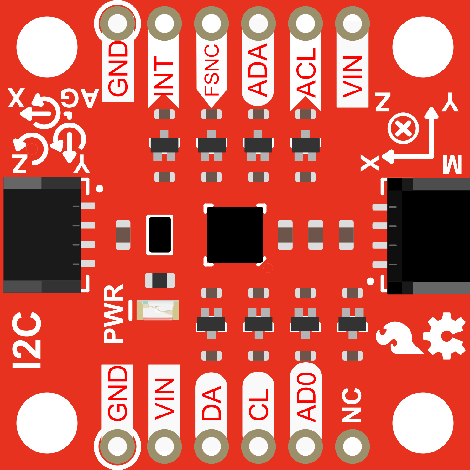
Pin Configuration and Descriptions

Pin Number Pin Name Description
1 VDD Power supply (1.71V to 3.6V)
2 GND Ground
3 SDA I2C Data Line / SPI Serial Data In (SDI)
4 SCL I2C Clock Line / SPI Serial Clock (SCK)
5 NCS SPI Chip Select (Active Low)
6 AUX_DA Auxiliary I2C Data Line
7 AUX_CL Auxiliary I2C Clock Line
8 FSYNC Frame Synchronization (Active Low)
9 INT Interrupt (Active Low)

Usage Instructions

How to Use the Component in a Circuit

  1. Powering the Device: Connect the VDD pin to a power supply within the specified voltage range and connect the GND pin to the ground of your system.
  2. Communication: Choose between I2C or SPI for communication. For I2C, connect SDA and SCL to your microcontroller's corresponding pins. For SPI, connect SDA (SDI), SCL (SCK), and NCS to the respective SPI pins on your microcontroller.
  3. Interrupts: The INT pin can be connected to an interrupt-capable GPIO pin on your microcontroller to handle interrupt-driven events.
  4. Frame Synchronization: The FSYNC pin is optional and can be used for advanced synchronization purposes.

Important Considerations and Best Practices

  • Ensure that the power supply is stable and within the specified voltage range to prevent damage to the IMU.
  • Use pull-up resistors on the I2C lines if they are not already present on your microcontroller board.
  • When using SPI, ensure that the NCS line is held high when the device is not in use.
  • For accurate readings, calibrate the magnetometer in the environment where it will be used.

Troubleshooting and FAQs

Common Issues Users Might Face

  • Inaccurate Readings: Ensure that the IMU is calibrated correctly. Avoid placing the IMU near magnetic or metallic objects that could interfere with the magnetometer.
  • Communication Errors: Check the wiring and ensure that the correct communication protocol (I2C or SPI) is selected in your code. Also, verify that the pull-up resistors are in place for I2C communication.

Solutions and Tips for Troubleshooting

  • No Data Output: Verify that the power supply is within the specified range and that all connections are secure.
  • Intermittent Connection: Check for loose wires or solder joints. Ensure that the pins are not shorting to each other.

FAQs

Q: Can I use multiple ICM-20948 IMUs on the same I2C bus? A: Yes, the ICM-20948 has an I2C address selection pin that allows for multiple devices on the same bus.

Q: How do I calibrate the magnetometer? A: Calibration typically involves rotating the IMU in various orientations and using software to compute the calibration parameters.

Q: What is the default I2C address of the ICM-20948? A: The default I2C address is 0x69, which can be changed to 0x68 when the AD0 pin is grounded.

Example Code for Arduino UNO

Below is a simple example of how to initialize the ICM-20948 using the I2C protocol with an Arduino UNO. This code assumes the use of a library that handles the low-level communication and sensor fusion.

#include <Wire.h>
#include <SparkFun_ICM-20948_IMU.h>

ICM_20948_I2C myIMU; // Create an ICM-20948 object

void setup() {
  Wire.begin();
  Serial.begin(115200);

  // Initialize the IMU
  if (myIMU.begin() != ICM_20948_Stat_Ok) {
    Serial.println("ICM-20948 initialization failed");
    while (1);
  }
  Serial.println("ICM-20948 initialization successful");
}

void loop() {
  // Check if new data is available
  if (myIMU.dataReady()) {
    myIMU.getAGMT(); // Get accelerometer, gyroscope, magnetometer, and temperature data

    // Print the accelerometer values
    Serial.print("Accel X: ");
    Serial.print(myIMU.accX());
    Serial.print(" Y: ");
    Serial.print(myIMU.accY());
    Serial.print(" Z: ");
    Serial.println(myIMU.accZ());

    // Add similar statements to print gyroscope and magnetometer data
  }
  delay(100); // Adjust the delay as needed
}

Note: This example assumes the existence of a library named SparkFun_ICM-20948_IMU.h which provides the necessary functions to interact with the ICM-20948. You will need to install the appropriate library through the Arduino Library Manager before compiling this code.