How to Use DHT11 Temperature & Humidity Sensor: Examples, Pinouts, and Specs
Introduction
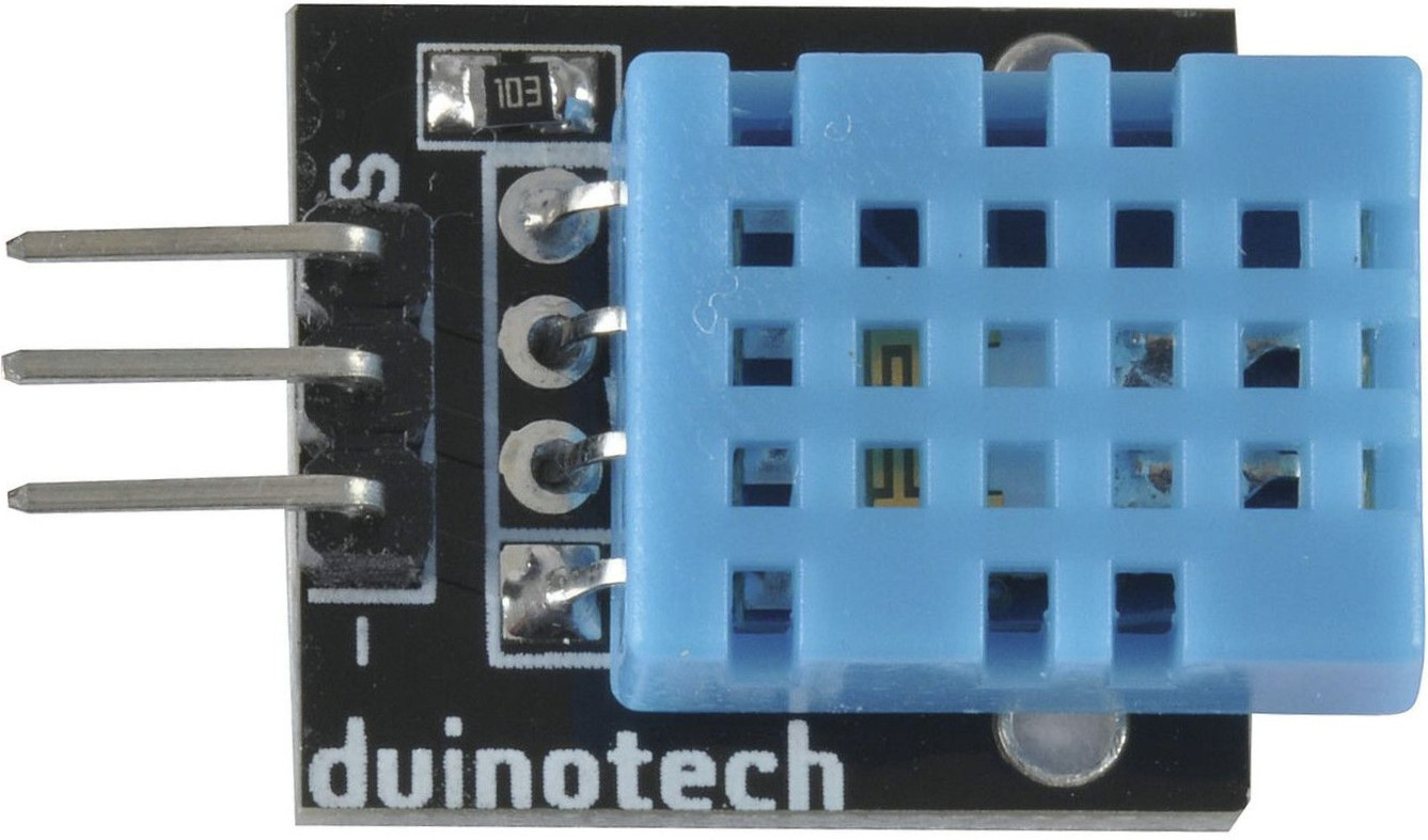
The DHT11 Temperature & Humidity Sensor (Manufacturer: Duinotech, Part ID: XC4520) is a low-cost, digital sensor designed to measure temperature and humidity. It provides reliable and accurate readings, making it ideal for a wide range of applications. The sensor outputs data in a digital format, simplifying integration with microcontrollers and development boards.
Explore Projects Built with DHT11 Temperature & Humidity Sensor
Explore Projects Built with DHT11 Temperature & Humidity Sensor
Common Applications
- Weather monitoring systems
- HVAC (Heating, Ventilation, and Air Conditioning) control
- Home automation projects
- Greenhouse monitoring
- IoT (Internet of Things) devices
Technical Specifications
The DHT11 sensor is designed for ease of use and reliable performance. Below are its key technical details:
| Parameter | Value |
|---|---|
| Supply Voltage | 3.3V to 5.5V |
| Operating Current | 0.3mA (measuring), 60µA (standby) |
| Temperature Range | 0°C to 50°C |
| Temperature Accuracy | ±2°C |
| Humidity Range | 20% to 90% RH |
| Humidity Accuracy | ±5% RH |
| Output Signal | Digital (1-wire protocol) |
| Sampling Period | 1 second |
| Dimensions | 15mm x 12mm x 5mm |
Pin Configuration
The DHT11 sensor has four pins, but typically only three are used in most applications. Below is the pinout:
| Pin Number | Name | Description |
|---|---|---|
| 1 | VCC | Power supply (3.3V to 5.5V) |
| 2 | DATA | Digital data output (connect to microcontroller) |
| 3 | NC (Not Connected) | Not used |
| 4 | GND | Ground (0V reference) |
Note: Some DHT11 modules may have only three pins (VCC, DATA, GND) with an onboard pull-up resistor.
Usage Instructions
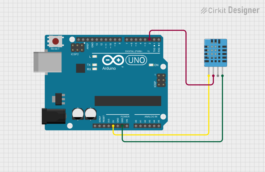
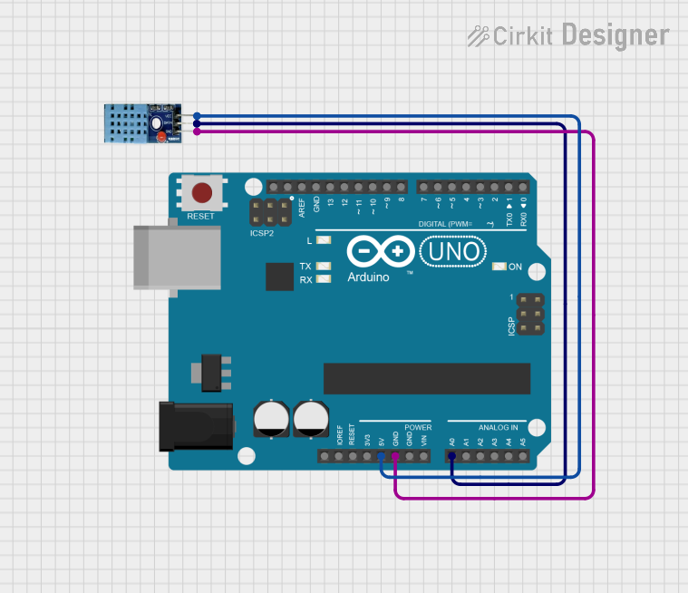
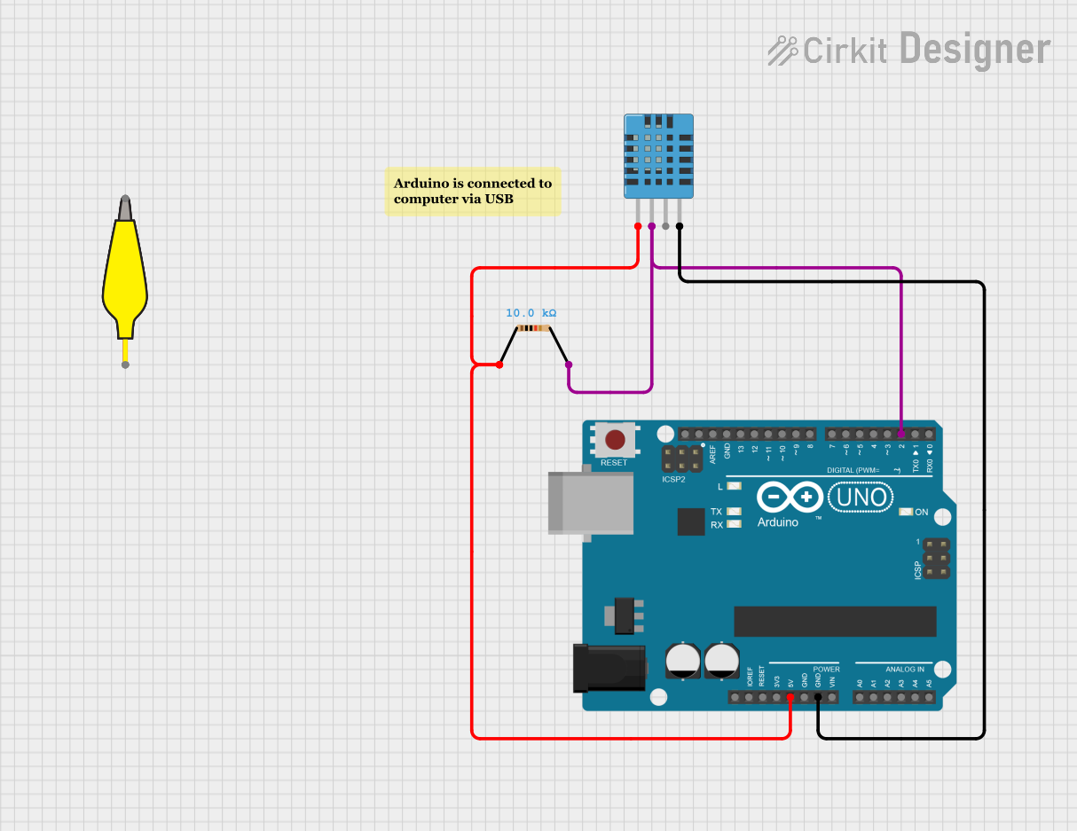
Connecting the DHT11 to a Circuit
- Power Supply: Connect the VCC pin to a 3.3V or 5V power source and the GND pin to ground.
- Data Line: Connect the DATA pin to a digital input pin on your microcontroller. Use a 10kΩ pull-up resistor between the DATA pin and VCC to ensure stable communication.
- Timing: The DHT11 requires a 1-second interval between readings to ensure accurate data.
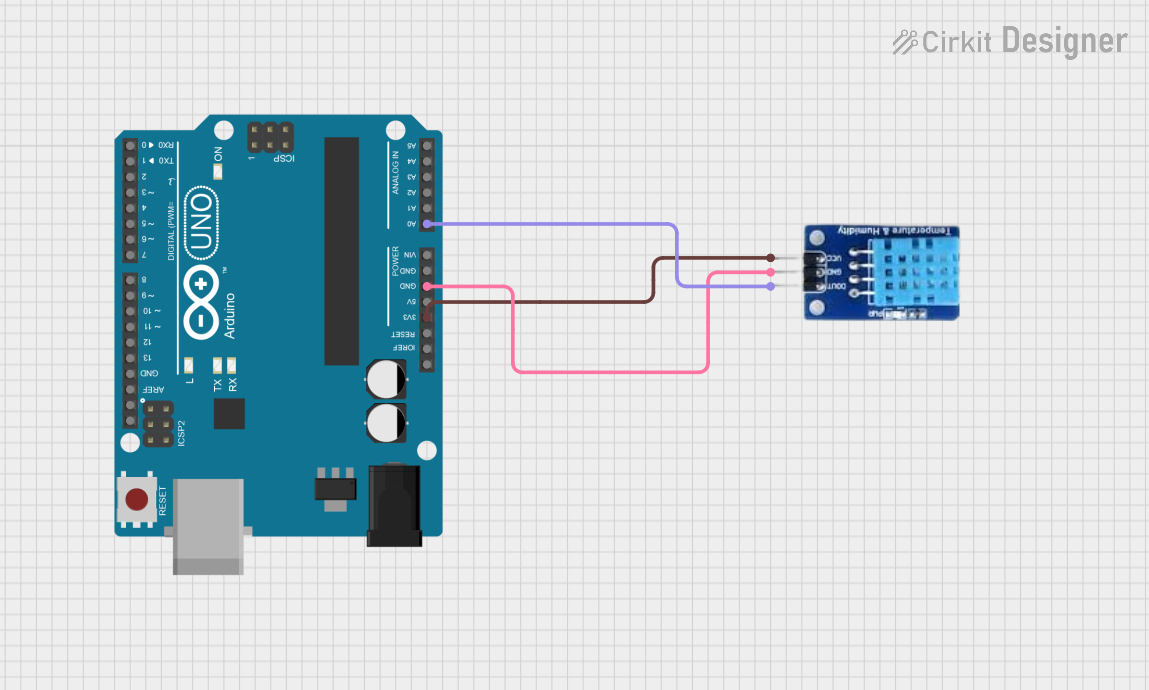
Example: Using the DHT11 with Arduino UNO
Below is an example of how to use the DHT11 sensor with an Arduino UNO. This code reads temperature and humidity values and displays them on the Serial Monitor.
Arduino Code
#include "DHT.h"  // Include the DHT library

#define DHTPIN 2    // Pin connected to the DATA pin of DHT11
#define DHTTYPE DHT11  // Define the sensor type (DHT11)

DHT dht(DHTPIN, DHTTYPE);  // Initialize the DHT sensor

void setup() {
  Serial.begin(9600);  // Start serial communication at 9600 baud
  Serial.println("DHT11 Sensor Initialization...");
  dht.begin();  // Initialize the DHT sensor
}

void loop() {
  delay(2000);  // Wait 2 seconds between readings

  float humidity = dht.readHumidity();  // Read humidity
  float temperature = dht.readTemperature();  // Read temperature in Celsius

  // Check if the readings are valid
  if (isnan(humidity) || isnan(temperature)) {
    Serial.println("Failed to read from DHT sensor!");
    return;
  }

  // Print the results to the Serial Monitor
  Serial.print("Humidity: ");
  Serial.print(humidity);
  Serial.print(" %\t");
  Serial.print("Temperature: ");
  Serial.print(temperature);
  Serial.println(" °C");
}
Best Practices
- Pull-up Resistor: Always use a pull-up resistor (10kΩ) on the DATA line to ensure stable communication.
- Sampling Interval: Avoid reading data more frequently than once per second to prevent inaccurate readings.
- Environmental Factors: Place the sensor in a location free from direct sunlight, condensation, or strong airflow for accurate measurements.
Troubleshooting and FAQs
Common Issues
No Data Output
- Cause: Incorrect wiring or missing pull-up resistor.
- Solution: Double-check the wiring and ensure a 10kΩ pull-up resistor is connected between the DATA pin and VCC.
Inaccurate Readings
- Cause: Sampling too frequently or environmental interference.
- Solution: Ensure a 1-second delay between readings and place the sensor in a stable environment.
"Failed to read from DHT sensor!" Error
- Cause: Loose connections or damaged sensor.
- Solution: Verify all connections and replace the sensor if necessary.
FAQs
Q: Can the DHT11 measure negative temperatures?
A: No, the DHT11 can only measure temperatures in the range of 0°C to 50°C.
Q: Can I use the DHT11 with a 3.3V microcontroller?
A: Yes, the DHT11 operates with a supply voltage range of 3.3V to 5.5V.
Q: What is the maximum cable length for the DHT11?
A: The maximum recommended cable length is 20 meters, but this depends on the quality of the cable and the pull-up resistor value.
Q: How does the DHT11 compare to the DHT22?
A: The DHT22 offers a wider temperature and humidity range with higher accuracy but is more expensive than the DHT11.
By following this documentation, you can effectively integrate the DHT11 sensor into your projects and troubleshoot common issues with ease.