
How to Use esp32 c3 super mini: Examples, Pinouts, and Specs
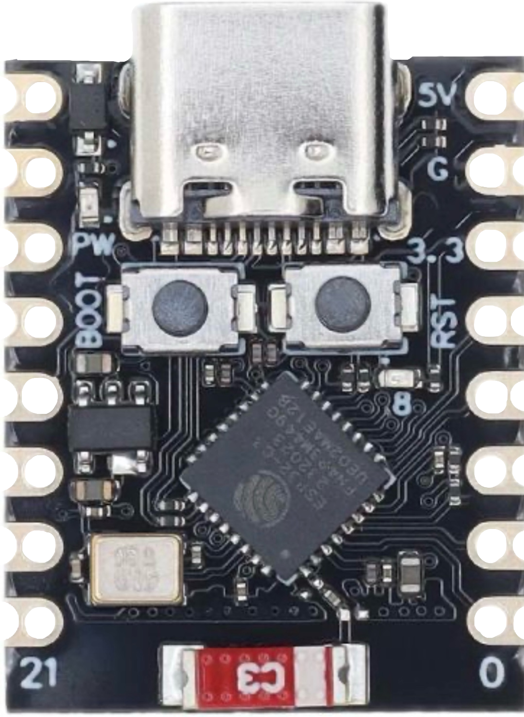
 Design with esp32 c3 super mini in Cirkit Designer
Introduction
The ESP32-C3 Super Mini, manufactured by Espressif, is a compact and powerful microcontroller designed for IoT applications. It features integrated Wi-Fi and Bluetooth Low Energy (BLE) capabilities, making it an excellent choice for projects requiring wireless connectivity. With its RISC-V single-core processor, low power consumption, and robust security features, the ESP32-C3 Super Mini is ideal for smart home devices, wearables, industrial automation, and other embedded systems.
Explore Projects Built with esp32 c3 super mini
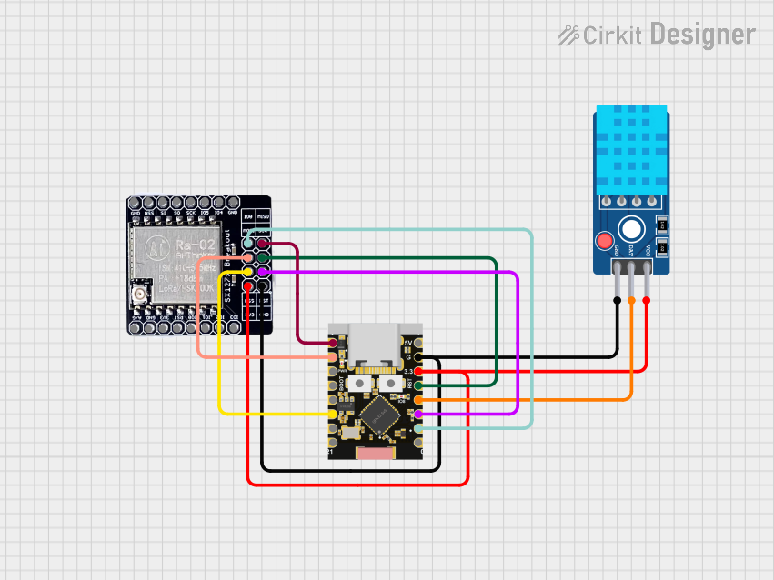 Open Project in Cirkit Designer
 Open Project in Cirkit Designer
 Open Project in Cirkit Designer
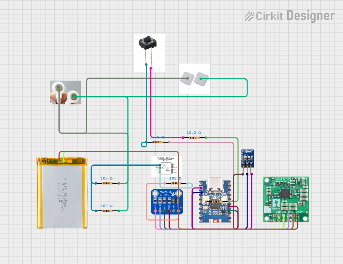 Open Project in Cirkit Designer
Explore Projects Built with esp32 c3 super mini
Open Project in Cirkit DesignerOpen Project in Cirkit DesignerOpen Project in Cirkit DesignerOpen Project in Cirkit DesignerCommon Applications
- IoT devices and smart home automation
- Wearable electronics
- Wireless sensor networks
- Industrial control systems
- Prototyping and educational projects
Technical Specifications
The ESP32-C3 Super Mini offers a range of features and specifications that make it versatile and efficient for various applications.
Key Technical Details
| Parameter | Specification |
|---|---|
| Processor | RISC-V single-core, 32-bit, 160 MHz |
| Flash Memory | 4 MB (varies by model) |
| RAM | 400 KB SRAM |
| Wi-Fi | IEEE 802.11 b/g/n (2.4 GHz) |
| Bluetooth | Bluetooth 5.0 LE |
| Operating Voltage | 3.3V |
| GPIO Pins | Up to 22 |
| ADC Channels | 6 (12-bit resolution) |
| UART | 2 |
| SPI | 2 |
| I2C | 1 |
| Power Consumption | Ultra-low power in deep sleep mode |
| Security Features | AES-128/256, SHA-256, RSA, HMAC |
| Dimensions | 18 mm x 21 mm |
Pin Configuration and Descriptions
The ESP32-C3 Super Mini has a compact pinout. Below is the pin configuration:
| Pin Number | Pin Name | Description |
|---|---|---|
| 1 | GND | Ground |
| 2 | 3V3 | 3.3V Power Supply |
| 3 | GPIO0 | General Purpose I/O, Boot Mode Select |
| 4 | GPIO1 | General Purpose I/O |
| 5 | GPIO2 | General Purpose I/O |
| 6 | GPIO3 | General Purpose I/O |
| 7 | GPIO4 | General Purpose I/O |
| 8 | GPIO5 | General Purpose I/O |
| 9 | RXD | UART Receive |
| 10 | TXD | UART Transmit |
| 11 | ADC1_CH0 | Analog Input Channel 0 |
| 12 | ADC1_CH1 | Analog Input Channel 1 |
Note: The exact pinout may vary slightly depending on the specific ESP32-C3 Super Mini module variant.
Usage Instructions
The ESP32-C3 Super Mini is easy to integrate into a variety of projects. Below are the steps and best practices for using this microcontroller.
How to Use the ESP32-C3 Super Mini in a Circuit
- Power Supply: Provide a stable 3.3V power supply to the
3V3pin. Ensure the current rating of the power source meets the module's requirements. - Boot Mode: To enter bootloader mode for programming, connect
GPIO0toGNDduring power-up or reset. - GPIO Usage: Use the GPIO pins for digital input/output, PWM, or other peripheral functions. Refer to the pin configuration table for specific pin capabilities.
- Wi-Fi and Bluetooth: Use the integrated Wi-Fi and BLE for wireless communication. Libraries such as
WiFiandBLEin the Arduino IDE simplify this process.
Important Considerations
- Voltage Levels: Ensure all connected peripherals operate at 3.3V logic levels to avoid damaging the module.
- Antenna Placement: For optimal wireless performance, avoid placing metal objects or other components near the onboard antenna.
- Deep Sleep Mode: Use deep sleep mode to minimize power consumption in battery-powered applications.
Example Code for Arduino UNO
The ESP32-C3 Super Mini can be programmed using the Arduino IDE. Below is an example of connecting to a Wi-Fi network:
#include <WiFi.h> // Include the Wi-Fi library for ESP32

const char* ssid = "Your_SSID";       // Replace with your Wi-Fi network name
const char* password = "Your_Password"; // Replace with your Wi-Fi password

void setup() {
  Serial.begin(115200); // Initialize serial communication at 115200 baud
  delay(1000);          // Wait for a moment to stabilize

  Serial.println("Connecting to Wi-Fi...");
  WiFi.begin(ssid, password); // Start Wi-Fi connection

  while (WiFi.status() != WL_CONNECTED) {
    delay(500); // Wait for connection
    Serial.print(".");
  }

  Serial.println("\nWi-Fi connected!");
  Serial.print("IP Address: ");
  Serial.println(WiFi.localIP()); // Print the assigned IP address
}

void loop() {
  // Add your main code here
}
Tip: Install the ESP32 board package in the Arduino IDE before uploading the code. Go to
File > Preferences, add the ESP32 board URL, and install the package via the Board Manager.
Troubleshooting and FAQs
Common Issues and Solutions
Wi-Fi Connection Fails
- Cause: Incorrect SSID or password.
- Solution: Double-check the credentials in your code and ensure the Wi-Fi network is active.
Module Not Detected in Arduino IDE
- Cause: Missing or incorrect board configuration.
- Solution: Install the ESP32 board package in the Arduino IDE and select the correct board and port.
GPIO Pins Not Responding
- Cause: Incorrect pin configuration or voltage mismatch.
- Solution: Verify the pin mode in your code and ensure peripherals operate at 3.3V logic levels.
High Power Consumption
- Cause: Module not in deep sleep mode.
- Solution: Use the
esp_deep_sleep_start()function to enable deep sleep mode.
FAQs
Q: Can the ESP32-C3 Super Mini be powered by USB?
A: Yes, if the module includes a USB interface, it can be powered and programmed via USB.Q: Does the ESP32-C3 support OTA updates?
A: Yes, the ESP32-C3 supports Over-The-Air (OTA) firmware updates.Q: Can I use the ESP32-C3 with 5V peripherals?
A: No, the ESP32-C3 operates at 3.3V logic levels. Use a level shifter for 5V peripherals.
By following this documentation, you can effectively integrate the ESP32-C3 Super Mini into your projects and troubleshoot common issues.