Cirkit Designer Logo
Cirkit Designer
Your all-in-one circuit design IDE
Home / 
Component Documentation

How to Use 16x32 p10 led matrix display: Examples, Pinouts, and Specs

Image of 16x32 p10 led matrix display
Cirkit Designer LogoDesign with 16x32 p10 led matrix display in Cirkit Designer

Introduction

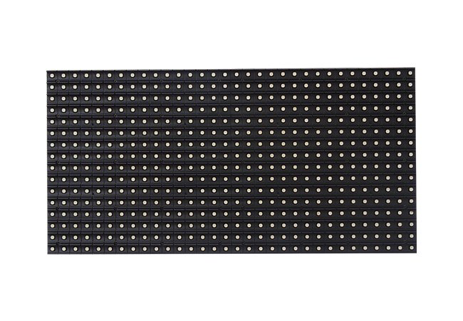
The 16x32 P10 LED Matrix Display is a versatile and vibrant display panel that consists of 16 rows and 32 columns of P10 (10mm pitch) RGB LED modules. This type of display is widely used in outdoor settings for advertising, information boards, and public event screens due to its high brightness and ability to show clear messages, animations, and graphics even in direct sunlight.

Explore Projects Built with 16x32 p10 led matrix display

Use Cirkit Designer to design, explore, and prototype these projects online. Some projects support real-time simulation. Click "Open Project" to start designing instantly!
Voice-Controlled P10 LED Matrix Display with Arduino and Bluetooth
Image of mini project: A project utilizing 16x32 p10 led matrix display in a practical application
This circuit features an Arduino UNO microcontroller interfaced with a 16x32 P10 LED matrix display and an HC-05 Bluetooth module. The Arduino receives voice commands via Bluetooth, processes them, and controls the LED matrix to display corresponding messages. A 5V power supply provides power to the Arduino and the LED matrix, while the AC supply is converted to DC for the power supply unit.
Cirkit Designer LogoOpen Project in Cirkit Designer
ESP32-Controlled Dual 8x8 LED Matrix Display with NTP Time Synchronization
Image of time: A project utilizing 16x32 p10 led matrix display in a practical application
This circuit features an ESP32 microcontroller connected to two cascaded 8x8 LED matrix displays, powered by a 3.3V battery. The ESP32 drives the displays to show time and other information, with the code indicating functionality for connecting to WiFi, synchronizing time via NTP, and displaying data on the matrices using custom fonts. Additionally, there is a separate 3.3V battery powering a red LED, which appears to function as a simple indicator light.
Cirkit Designer LogoOpen Project in Cirkit Designer
Arduino UNO-Based Interactive LED Game with 8x8 Matrix and TM1637 Display
Image of Gra_na_refleks: A project utilizing 16x32 p10 led matrix display in a practical application
This circuit is a game system controlled by an Arduino UNO, featuring an 8x8 LED matrix, a 4x4 keypad, and a TM1637 4-digit display. The user interacts with the game via the keypad, and the game state is displayed on the LED matrix and the TM1637 display, with power supplied by a 9V battery.
Cirkit Designer LogoOpen Project in Cirkit Designer
Arduino UNO Controlled LED Matrix and LCD Interface with Joystick Interaction
Image of Digital Game Circuit: A project utilizing 16x32 p10 led matrix display in a practical application
This circuit features an Arduino UNO microcontroller interfaced with an 8x8 LED matrix, an LCD screen, and a KY-023 Dual Axis Joystick Module. The Arduino controls the LED matrix via digital pins D10-D12 and powers the matrix, LCD, and joystick module from its 5V output. The joystick's analog outputs are connected to the Arduino's analog inputs A0 and A1 for position sensing, while the LCD is controlled through digital pins D2-D6 and D13 for display purposes.
Cirkit Designer LogoOpen Project in Cirkit Designer

Explore Projects Built with 16x32 p10 led matrix display

Use Cirkit Designer to design, explore, and prototype these projects online. Some projects support real-time simulation. Click "Open Project" to start designing instantly!
Image of mini project: A project utilizing 16x32 p10 led matrix display in a practical application
Voice-Controlled P10 LED Matrix Display with Arduino and Bluetooth
This circuit features an Arduino UNO microcontroller interfaced with a 16x32 P10 LED matrix display and an HC-05 Bluetooth module. The Arduino receives voice commands via Bluetooth, processes them, and controls the LED matrix to display corresponding messages. A 5V power supply provides power to the Arduino and the LED matrix, while the AC supply is converted to DC for the power supply unit.
Cirkit Designer LogoOpen Project in Cirkit Designer
Image of time: A project utilizing 16x32 p10 led matrix display in a practical application
ESP32-Controlled Dual 8x8 LED Matrix Display with NTP Time Synchronization
This circuit features an ESP32 microcontroller connected to two cascaded 8x8 LED matrix displays, powered by a 3.3V battery. The ESP32 drives the displays to show time and other information, with the code indicating functionality for connecting to WiFi, synchronizing time via NTP, and displaying data on the matrices using custom fonts. Additionally, there is a separate 3.3V battery powering a red LED, which appears to function as a simple indicator light.
Cirkit Designer LogoOpen Project in Cirkit Designer
Image of Gra_na_refleks: A project utilizing 16x32 p10 led matrix display in a practical application
Arduino UNO-Based Interactive LED Game with 8x8 Matrix and TM1637 Display
This circuit is a game system controlled by an Arduino UNO, featuring an 8x8 LED matrix, a 4x4 keypad, and a TM1637 4-digit display. The user interacts with the game via the keypad, and the game state is displayed on the LED matrix and the TM1637 display, with power supplied by a 9V battery.
Cirkit Designer LogoOpen Project in Cirkit Designer
Image of Digital Game Circuit: A project utilizing 16x32 p10 led matrix display in a practical application
Arduino UNO Controlled LED Matrix and LCD Interface with Joystick Interaction
This circuit features an Arduino UNO microcontroller interfaced with an 8x8 LED matrix, an LCD screen, and a KY-023 Dual Axis Joystick Module. The Arduino controls the LED matrix via digital pins D10-D12 and powers the matrix, LCD, and joystick module from its 5V output. The joystick's analog outputs are connected to the Arduino's analog inputs A0 and A1 for position sensing, while the LCD is controlled through digital pins D2-D6 and D13 for display purposes.
Cirkit Designer LogoOpen Project in Cirkit Designer

Common Applications and Use Cases

  • Outdoor advertising billboards
  • Public information displays
  • Scoreboards for sports events
  • Concert and event visuals
  • Customizable signs for shops and businesses

Technical Specifications

Key Technical Details

  • Resolution: 16 rows x 32 columns
  • Pitch: P10 (10mm between each LED center)
  • Module Size: Typically 320mm x 160mm
  • Color: Full RGB color support
  • Brightness: Suitable for outdoor visibility
  • Operating Voltage: 5V DC
  • Maximum Current: Varies depending on brightness and color content

Pin Configuration and Descriptions

Pin Number Description Notes
1 R1 (Red Data 1) Red data for top half of the panel
2 G1 (Green Data 1) Green data for top half of the panel
3 B1 (Blue Data 1) Blue data for top half of the panel
4 R2 (Red Data 2) Red data for bottom half of the panel
5 G2 (Green Data 2) Green data for bottom half of the panel
6 B2 (Blue Data 2) Blue data for bottom half of the panel
7 A (Address A) Row address line A
8 B (Address B) Row address line B
9 C (Address C) Row address line C
10 D (Address D) Row address line D (if applicable)
11 CLK (Clock) Clock signal for data latching
12 LAT (Latch) Latch signal to update display
13 OE (Output Enable) Enables output to the LEDs
14 GND (Ground) Ground connection

Usage Instructions

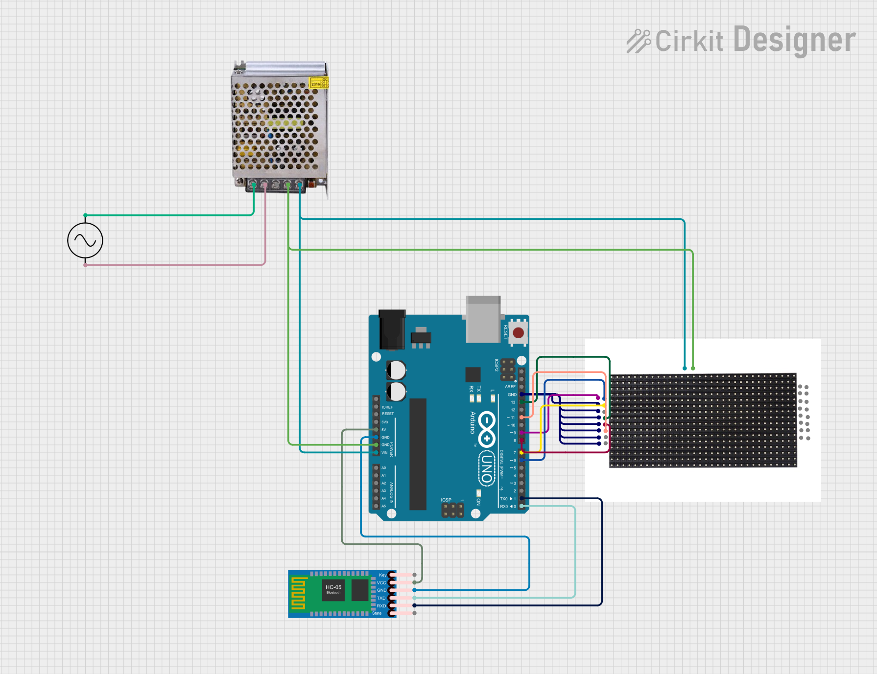
How to Use the Component in a Circuit

  1. Power Supply: Ensure you have a stable 5V power supply that can handle the maximum current draw of the display.
  2. Data Connection: Connect the data input pins (R1, G1, B1, R2, G2, B2) to the corresponding output pins on your controller.
  3. Addressing: Connect the address lines (A, B, C, D) to your controller to select the row to be activated.
  4. Control Signals: Connect the CLK, LAT, and OE pins to your controller to manage the timing of data updates to the display.

Important Considerations and Best Practices

  • Power: Always provide adequate power to the display. Insufficient power can lead to dim or uneven lighting.
  • Heat Dissipation: Ensure proper heat dissipation to prevent damage to the LEDs.
  • Weatherproofing: If used outdoors, make sure the display is enclosed in a weatherproof casing.
  • Refresh Rate: To prevent flickering, maintain an appropriate refresh rate, typically above 400Hz.

Troubleshooting and FAQs

Common Issues Users Might Face

  • Dim Display: Check the power supply for adequate voltage and current.
  • Uneven Colors: Ensure that data connections are secure and that there is no voltage drop across the data lines.
  • Flickering: Increase the refresh rate or check for loose connections.

Solutions and Tips for Troubleshooting

  • Power Issues: Use a multimeter to verify the power supply voltage and current.
  • Connection Issues: Re-seat all connections and ensure solid solder joints.
  • Refresh Rate: Adjust the refresh rate in the controller software settings.

FAQs

Q: Can I chain multiple panels together? A: Yes, panels can be daisy-chained to create larger displays. Ensure your controller can handle the increased data rate.

Q: How do I control the display with an Arduino? A: You can use libraries such as the Adafruit GFX library along with an appropriate driver shield or board designed for LED matrices.

Q: What is the maximum distance I can place the controller from the display? A: It depends on the signal integrity and power supply. Use shorter distances for reliable performance or use signal repeaters for longer distances.

Q: How do I program animations or text? A: You can use drawing functions provided by the controller's library to program animations or text. Pre-rendered animations can be stored in memory and displayed frame by frame.

Q: Can the display be used indoors? A: Yes, but it may be excessively bright for indoor use. Adjust the brightness accordingly.

Example Arduino Code

Below is a simple example of how to interface the 16x32 P10 LED Matrix Display with an Arduino UNO using the Adafruit GFX library. This code initializes the display and shows a scrolling text message.

#include <Adafruit_GFX.h>   // Core graphics library
#include <RGBmatrixPanel.h>  // Hardware-specific library

#define CLK  8   // MUST be on PORTB! (Use pin 11 on Mega)
#define LAT 10
#define OE   9
#define A   A0
#define B   A1
#define C   A2
#define D   A3  // Only required for 1/32 scan panels

// 16x32 RGB LED matrix panel instance
RGBmatrixPanel matrix(A, B, C, D, CLK, LAT, OE, false);

void setup() {
  matrix.begin();
  matrix.setTextWrap(false);  // Allow text to run off right edge
  matrix.setTextSize(1);
  matrix.setTextColor(matrix.Color333(7, 7, 7));
}

void loop() {
  // Scroll text to the left
  for (int i = 0; i < 128; i++) {
    matrix.fillScreen(0);
    matrix.setCursor(32 - i, 0);
    matrix.print(F("Hello, World!"));
    matrix.swapBuffers(false);
    delay(50);
  }
}

Remember to adjust the pin definitions to match your actual wiring and modify the text and graphics as desired.