Cirkit Designer Logo
Cirkit Designer
Your all-in-one circuit design IDE
Home / 
Component Documentation

How to Use Capteur de courant: Examples, Pinouts, and Specs

Image of Capteur de courant
Cirkit Designer LogoDesign with Capteur de courant in Cirkit Designer

Introduction

The Capteur de courant (current sensor) is a device designed to detect and measure the flow of electric current in a circuit. Manufactured by Arduino with the part ID "UNO," this sensor is widely used in applications requiring current monitoring and control. It provides accurate and real-time current measurements, making it ideal for projects involving power management, motor control, and energy monitoring.

Explore Projects Built with Capteur de courant

Use Cirkit Designer to design, explore, and prototype these projects online. Some projects support real-time simulation. Click "Open Project" to start designing instantly!
ESP32-Based Automatic Passenger Counter and Temperature Sensor with Wi-Fi Connectivity
Image of Embedded Circuit: A project utilizing Capteur de courant in a practical application
This circuit is an automatic passenger counter and temperature sensor system powered by a solar charger. It uses an ESP32 microcontroller to interface with two capacitive proximity sensors for counting passengers and a DHT22 sensor for monitoring temperature and humidity, with data being sent to a Blynk mobile app and Google Sheets for real-time tracking and logging.
Cirkit Designer LogoOpen Project in Cirkit Designer
ESP32-Based Voltage and Current Monitoring System with Wi-Fi Connectivity
Image of Sustainability: A project utilizing Capteur de courant in a practical application
This circuit is designed to measure and monitor voltage and current using an ESP32 microcontroller. It includes a voltage sensor and a current sensor connected to the ESP32, which reads the sensor data and outputs the measurements to the Serial Monitor. The circuit also features a power supply system with an AC source, a transformer, and a bridge rectifier to provide the necessary DC voltage for the sensors and microcontroller.
Cirkit Designer LogoOpen Project in Cirkit Designer
STM32 Nucleo F303RE Based Current Monitoring System with LCD Display
Image of Project BMS: A project utilizing Capteur de courant in a practical application
This circuit features a current sensor connected to a 7V battery, with the sensor's output connected to an STM32 Nucleo F303RE microcontroller for current monitoring. An NTC thermistor is interfaced with the microcontroller for temperature sensing, and a 16x2 LCD screen is connected via I2C for data display. The circuit includes various resistors for voltage division and current limiting purposes.
Cirkit Designer LogoOpen Project in Cirkit Designer
ESP32-Based Smart Energy Monitoring and Control System
Image of SMART SOCKET: A project utilizing Capteur de courant in a practical application
This circuit is designed to monitor AC voltage and current using ZMPT101B and ZMCT103C sensors, respectively, with an ESP32 microcontroller processing the sensor outputs. The XL4015 step-down module regulates the power supply to provide a stable voltage to the sensors, the ESP32, and an LCD I2C display. The ESP32 controls a 4-channel relay module for switching AC loads, and the system's operation can be interacted with via the LCD display and a push switch.
Cirkit Designer LogoOpen Project in Cirkit Designer

Explore Projects Built with Capteur de courant

Use Cirkit Designer to design, explore, and prototype these projects online. Some projects support real-time simulation. Click "Open Project" to start designing instantly!
Image of Embedded Circuit: A project utilizing Capteur de courant in a practical application
ESP32-Based Automatic Passenger Counter and Temperature Sensor with Wi-Fi Connectivity
This circuit is an automatic passenger counter and temperature sensor system powered by a solar charger. It uses an ESP32 microcontroller to interface with two capacitive proximity sensors for counting passengers and a DHT22 sensor for monitoring temperature and humidity, with data being sent to a Blynk mobile app and Google Sheets for real-time tracking and logging.
Cirkit Designer LogoOpen Project in Cirkit Designer
Image of Sustainability: A project utilizing Capteur de courant in a practical application
ESP32-Based Voltage and Current Monitoring System with Wi-Fi Connectivity
This circuit is designed to measure and monitor voltage and current using an ESP32 microcontroller. It includes a voltage sensor and a current sensor connected to the ESP32, which reads the sensor data and outputs the measurements to the Serial Monitor. The circuit also features a power supply system with an AC source, a transformer, and a bridge rectifier to provide the necessary DC voltage for the sensors and microcontroller.
Cirkit Designer LogoOpen Project in Cirkit Designer
Image of Project BMS: A project utilizing Capteur de courant in a practical application
STM32 Nucleo F303RE Based Current Monitoring System with LCD Display
This circuit features a current sensor connected to a 7V battery, with the sensor's output connected to an STM32 Nucleo F303RE microcontroller for current monitoring. An NTC thermistor is interfaced with the microcontroller for temperature sensing, and a 16x2 LCD screen is connected via I2C for data display. The circuit includes various resistors for voltage division and current limiting purposes.
Cirkit Designer LogoOpen Project in Cirkit Designer
Image of SMART SOCKET: A project utilizing Capteur de courant in a practical application
ESP32-Based Smart Energy Monitoring and Control System
This circuit is designed to monitor AC voltage and current using ZMPT101B and ZMCT103C sensors, respectively, with an ESP32 microcontroller processing the sensor outputs. The XL4015 step-down module regulates the power supply to provide a stable voltage to the sensors, the ESP32, and an LCD I2C display. The ESP32 controls a 4-channel relay module for switching AC loads, and the system's operation can be interacted with via the LCD display and a push switch.
Cirkit Designer LogoOpen Project in Cirkit Designer

Common Applications and Use Cases

  • Monitoring current in power supply circuits
  • Measuring current consumption in motors and appliances
  • Energy monitoring in renewable energy systems
  • Overcurrent protection in electronic devices
  • Battery management systems

Technical Specifications

The Capteur de courant is designed to work seamlessly with Arduino boards, including the Arduino UNO. Below are the key technical details:

Key Specifications

  • Operating Voltage: 5V DC
  • Current Measurement Range: -20A to +20A
  • Output Signal: Analog voltage proportional to current
  • Accuracy: ±1% (typical)
  • Sensitivity: 100mV/A
  • Response Time: <5 µs
  • Operating Temperature: -40°C to +85°C
  • Dimensions: 25mm x 20mm x 15mm

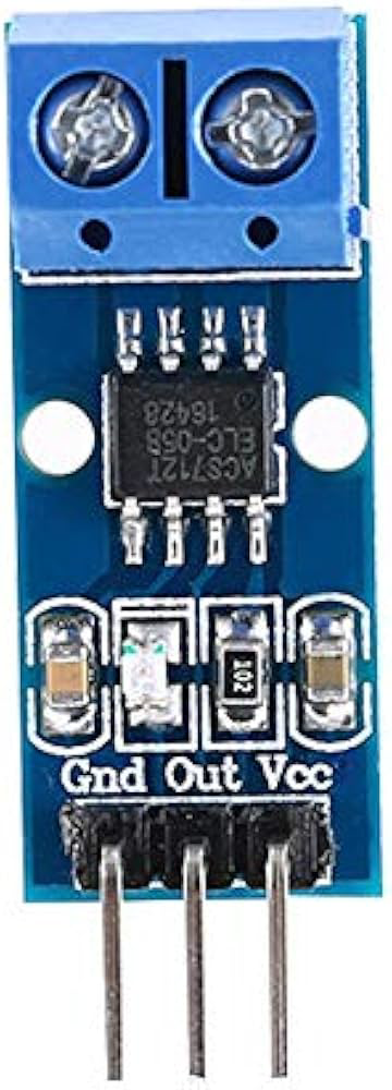
Pin Configuration and Descriptions

The Capteur de courant typically has three pins for connection. The table below describes each pin:

Pin Name Description
VCC Power supply input (5V DC)
GND Ground connection
OUT Analog output signal proportional to current

Usage Instructions

How to Use the Capteur de courant in a Circuit

  1. Connect the Sensor to the Arduino UNO:

    • Connect the VCC pin of the sensor to the 5V pin on the Arduino UNO.
    • Connect the GND pin of the sensor to the GND pin on the Arduino UNO.
    • Connect the OUT pin of the sensor to an analog input pin (e.g., A0) on the Arduino UNO.
  2. Place the Sensor in the Circuit:

    • Ensure the current-carrying wire passes through the sensor's detection area (if applicable).
    • For bidirectional current measurement, ensure the wire is properly aligned with the sensor's orientation.
  3. Read the Output:

    • Use the Arduino's analog-to-digital converter (ADC) to read the voltage from the OUT pin.
    • Convert the voltage reading to current using the sensor's sensitivity (e.g., 100mV/A).

Important Considerations and Best Practices

  • Ensure the sensor is powered with a stable 5V DC supply for accurate readings.
  • Avoid placing the sensor near strong magnetic fields, as they may interfere with measurements.
  • Use proper insulation and safety precautions when working with high-current circuits.
  • Calibrate the sensor if necessary to improve accuracy in your specific application.

Example Code for Arduino UNO

Below is an example Arduino sketch to read current values from the Capteur de courant:

// Define the analog pin connected to the sensor's OUT pin
const int sensorPin = A0;

// Define the sensor's sensitivity in mV per Ampere (100mV/A)
const float sensitivity = 0.1; // 100mV = 0.1V

void setup() {
  // Initialize serial communication for debugging
  Serial.begin(9600);
}

void loop() {
  // Read the analog value from the sensor
  int sensorValue = analogRead(sensorPin);

  // Convert the analog value to voltage (5V reference, 10-bit ADC)
  float voltage = sensorValue * (5.0 / 1023.0);

  // Calculate the current in Amperes
  float current = voltage / sensitivity;

  // Print the current value to the Serial Monitor
  Serial.print("Current: ");
  Serial.print(current);
  Serial.println(" A");

  // Wait for 500ms before the next reading
  delay(500);
}

Troubleshooting and FAQs

Common Issues and Solutions

  1. No Output or Incorrect Readings:

    • Cause: Incorrect wiring or loose connections.
    • Solution: Double-check all connections, ensuring the sensor is properly powered and connected to the Arduino.
  2. Fluctuating or Noisy Readings:

    • Cause: Electrical noise or interference.
    • Solution: Add a capacitor (e.g., 0.1µF) between the sensor's OUT pin and GND to filter noise.
  3. Readings Do Not Match Expected Values:

    • Cause: Calibration issue or incorrect sensitivity value.
    • Solution: Verify the sensor's sensitivity and calibrate the system using a known current source.
  4. Sensor Overheating:

    • Cause: Exceeding the sensor's current measurement range.
    • Solution: Ensure the current in the circuit does not exceed the sensor's maximum rating of ±20A.

FAQs

Q1: Can this sensor measure both AC and DC currents?
A1: Yes, the Capteur de courant can measure both AC and DC currents, but additional processing may be required for AC current measurements.

Q2: How do I improve the accuracy of the sensor?
A2: Use a stable power supply, minimize noise in the circuit, and calibrate the sensor with a known current source.

Q3: Can I use this sensor with microcontrollers other than Arduino?
A3: Yes, the sensor can be used with other microcontrollers, provided they have an analog input pin and a 5V power supply.

Q4: What happens if the current exceeds the sensor's range?
A4: The sensor may saturate, resulting in inaccurate readings. Prolonged exposure to excessive current may damage the sensor.