How to Use STA540: Examples, Pinouts, and Specs
Introduction
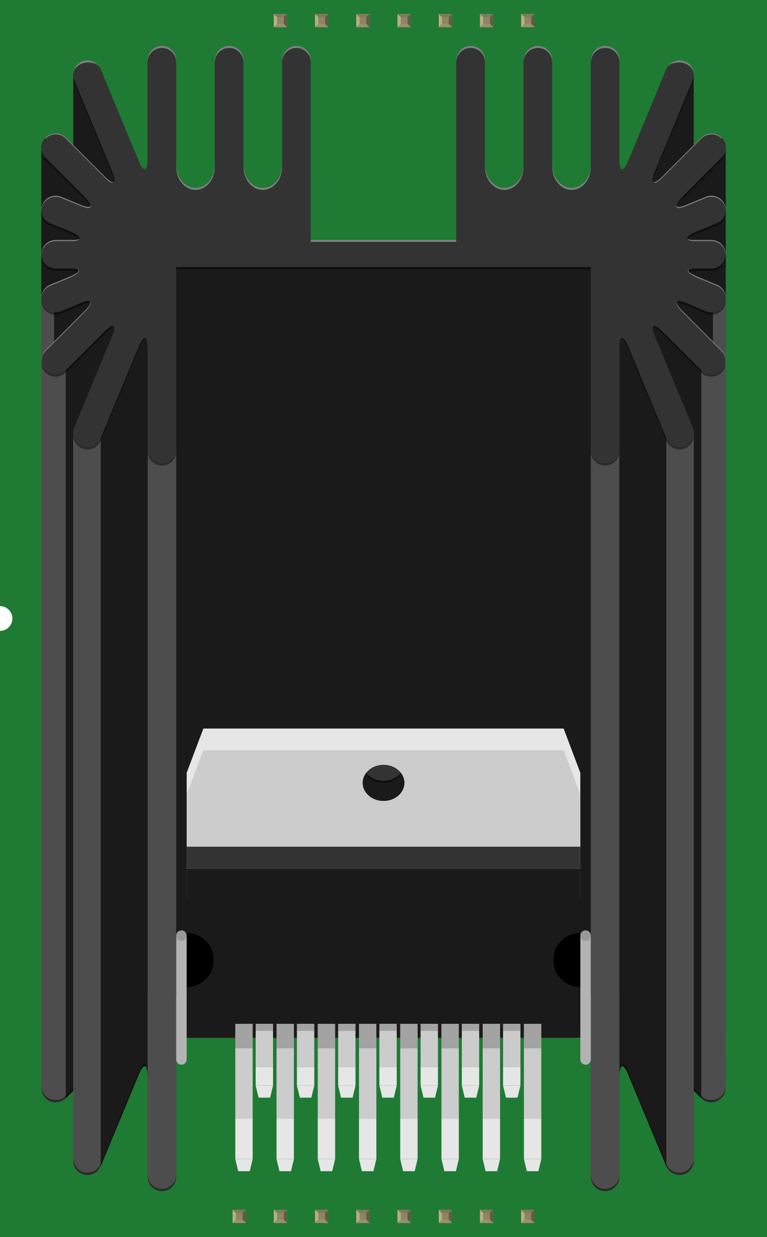
The STA540 is a dual/quad channel audio amplifier integrated circuit (IC) capable of delivering up to 38W of continuous average power to an 8 Ohm load with 0.1% THD+N from a 22V supply. With its high output power, low distortion, and integrated short-circuit and thermal protection, the STA540 is widely used in home stereo systems, active speakers, and DIY audio projects.
Explore Projects Built with STA540


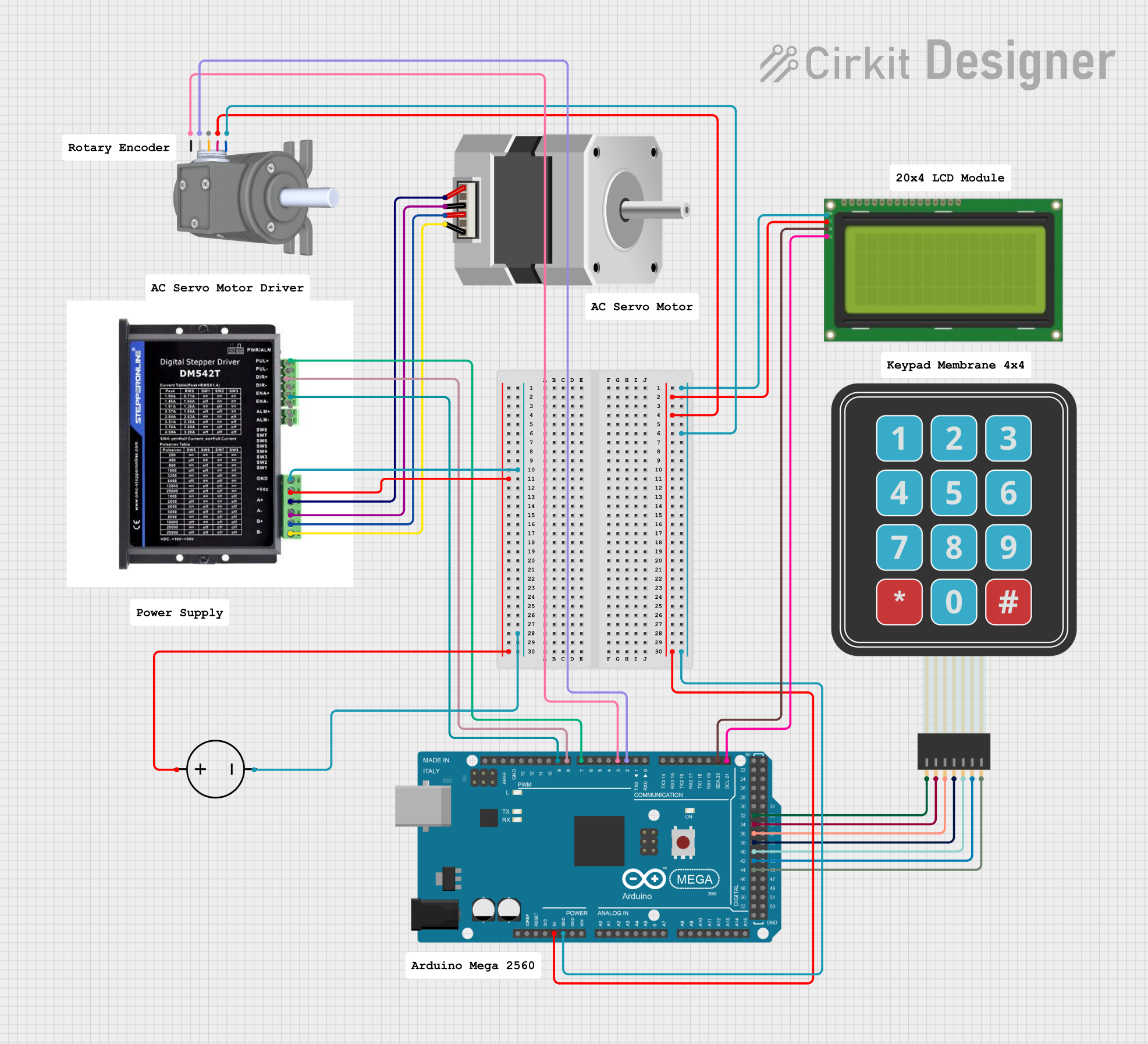

Explore Projects Built with STA540
Common Applications and Use Cases
- Home theater systems
- Active speaker systems
- DIY audio amplifiers
- Multi-channel audio systems
Technical Specifications
Key Technical Details
- Supply Voltage Range: 8V - 22V
- Output Power: Up to 38W per channel (8 Ohm load)
- Number of Channels: 4 (can be configured as dual or quad channel)
- Total Harmonic Distortion + Noise (THD+N): 0.1%
- Standby and Mute Functions
Pin Configuration and Descriptions
| Pin Number | Pin Name | Description |
|---|---|---|
| 1 | SVRR | Standby Voltage Rail Right |
| 2 | OUT1 | Output Channel 1 |
| 3 | VCC1 | Power Supply Voltage for Channels 1 and 2 |
| 4 | OUT2 | Output Channel 2 |
| 5 | GND | Ground Reference |
| 6 | OUT3 | Output Channel 3 |
| 7 | VCC2 | Power Supply Voltage for Channels 3 and 4 |
| 8 | OUT4 | Output Channel 4 |
| 9 | SVRL | Standby Voltage Rail Left |
| 10 | IN1 | Input Channel 1 |
| 11 | IN2 | Input Channel 2 |
| 12 | -Vs | Negative Supply Voltage |
| 13 | IN3 | Input Channel 3 |
| 14 | IN4 | Input Channel 4 |
| 15 | D95V | Diagnostic 9.5V Reference Voltage |
| 16 | STBY | Standby Control Input |
| 17 | MUTE | Mute Control Input |
| 18 | SVR | Standby Voltage Reference |
| 19 | DIAG | Diagnostic Output |
Usage Instructions
How to Use the STA540 in a Circuit
- Power Supply: Connect a suitable power supply to the VCC1 and VCC2 pins, ensuring it is within the 8V to 22V range.
- Input Signal: Apply the audio input signals to the IN1, IN2, IN3, and IN4 pins as required.
- Output Connection: Connect the OUT1, OUT2, OUT3, and OUT4 pins to the speakers, ensuring proper impedance matching.
- Standby and Mute: Use the STBY and MUTE pins to control the standby and mute functions, respectively. These can be connected to switches or controlled via a microcontroller.
- Grounding: Ensure all ground connections are made to the GND pin and that there is a common ground point to avoid ground loops.
Important Considerations and Best Practices
- Use decoupling capacitors close to the power supply pins to filter out noise and stabilize the voltage.
- Implement proper heat sinking for the IC to prevent thermal shutdown during high-power operation.
- Avoid long input and output wires to minimize the risk of oscillations and interference.
- Ensure that the speakers are rated for the output power that the STA540 will deliver.
Troubleshooting and FAQs
Common Issues
- No Sound Output: Check power supply, input connections, and ensure that the IC is not in standby or mute mode.
- Distorted Sound: Verify that the input signal is not too high, causing clipping. Also, check for proper power supply filtering.
- Overheating: Ensure adequate heat sinking and airflow around the IC. Check for short circuits or speaker impedance mismatches.
Solutions and Tips for Troubleshooting
- Power Cycling: If the IC enters protection mode, power cycle the device to reset its state.
- Signal Integrity: Use shielded cables for input signals and keep signal paths short to reduce noise pickup.
- Testing: Use a multimeter to check for correct voltages at the power supply and output pins.
FAQs
Q: Can the STA540 be bridged for more power? A: Yes, the STA540 can be configured in a bridged mode to increase output power. Refer to the manufacturer's datasheet for bridging instructions.
Q: What is the function of the DIAG pin? A: The DIAG pin provides diagnostic information regarding the IC's status, such as over-temperature or short-circuit conditions.
Q: How can I control the standby and mute functions with an Arduino? A: You can connect the STBY and MUTE pins to digital outputs on the Arduino and write HIGH or LOW to control these functions.
Example Arduino Code for Standby and Mute Control
// Define the pin numbers for standby and mute control
const int standbyPin = 2;
const int mutePin = 3;

void setup() {
  // Set the standby and mute pins as outputs
  pinMode(standbyPin, OUTPUT);
  pinMode(mutePin, OUTPUT);

  // Disable standby and mute by writing LOW
  digitalWrite(standbyPin, LOW);
  digitalWrite(mutePin, LOW);
}

void loop() {
  // Example: Enable mute for 5 seconds, then disable
  digitalWrite(mutePin, HIGH); // Enable mute
  delay(5000);                 // Wait for 5 seconds
  digitalWrite(mutePin, LOW);  // Disable mute
  delay(5000);                 // Wait for 5 seconds
}
Remember to keep the code comments concise and within the 80 character line length limit. This example demonstrates basic control of the STA540's standby and mute functions using an Arduino.