How to Use Level Converter: Examples, Pinouts, and Specs
Introduction
A level converter, also known as a logic level shifter, is a circuit component designed to translate signals between different voltage levels. This allows devices operating at different logic levels to communicate seamlessly. For example, it enables a 3.3V microcontroller to interface with a 5V sensor or peripheral.
Manufactured by Arduino, the Level Converter (Part ID: UNO) is a versatile and reliable solution for voltage level translation. It is commonly used in projects involving microcontrollers, sensors, and communication modules.
Explore Projects Built with Level Converter


Explore Projects Built with Level Converter
Common Applications and Use Cases
- Interfacing 3.3V microcontrollers (e.g., ESP32, Raspberry Pi) with 5V peripherals.
- Enabling communication between devices with different voltage standards (e.g., I2C, UART, SPI).
- Protecting low-voltage devices from damage caused by higher voltage signals.
- Translating signals for bidirectional communication in mixed-voltage systems.
Technical Specifications
Key Technical Details
- Voltage Range (Low Side): 1.8V to 3.3V
- Voltage Range (High Side): 3.3V to 5V
- Maximum Current per Channel: 50mA
- Number of Channels: 4 bidirectional channels
- Operating Temperature Range: -40°C to 85°C
- Dimensions: 15mm x 15mm x 3mm
- Communication Protocols Supported: I2C, UART, SPI, GPIO
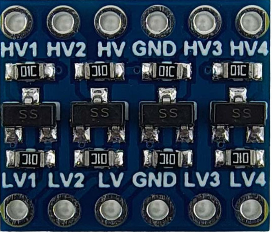
Pin Configuration and Descriptions
The Level Converter has a total of 8 pins, divided into two groups: Low Voltage (LV) side and High Voltage (HV) side.
| Pin Name | Description |
|---|---|
| LV | Low voltage power input (1.8V to 3.3V). Connect to the low-voltage device. |
| LV1 | Low voltage signal input/output channel 1. |
| LV2 | Low voltage signal input/output channel 2. |
| LV3 | Low voltage signal input/output channel 3. |
| LV4 | Low voltage signal input/output channel 4. |
| HV | High voltage power input (3.3V to 5V). Connect to the high-voltage device. |
| HV1 | High voltage signal input/output channel 1. |
| HV2 | High voltage signal input/output channel 2. |
| HV3 | High voltage signal input/output channel 3. |
| HV4 | High voltage signal input/output channel 4. |
| GND | Ground. Connect to the ground of both devices. |
Usage Instructions
How to Use the Component in a Circuit
Power Connections:
- Connect the LV pin to the low-voltage power supply (e.g., 3.3V).
- Connect the HV pin to the high-voltage power supply (e.g., 5V).
- Connect the GND pin to the ground of both the low-voltage and high-voltage devices.
Signal Connections:
- Connect the low-voltage device's signal lines to the LV1, LV2, LV3, or LV4 pins.
- Connect the high-voltage device's signal lines to the corresponding HV1, HV2, HV3, or HV4 pins.
Communication Protocols:
- For I2C communication, connect the SDA and SCL lines to any of the available channels.
- For UART or SPI, assign the appropriate TX, RX, MISO, MOSI, and CLK lines to the channels.
Important Considerations and Best Practices
- Ensure that the LV and HV power supplies are stable and within the specified voltage ranges.
- Do not exceed the maximum current rating of 50mA per channel.
- Use pull-up resistors for I2C communication if required by your devices.
- Verify the pinout of your devices before connecting them to the level converter.
- Avoid leaving unused channels floating; connect them to ground if not in use.
Example: Connecting to an Arduino UNO
Below is an example of using the Level Converter to interface a 3.3V sensor with an Arduino UNO (5V logic).
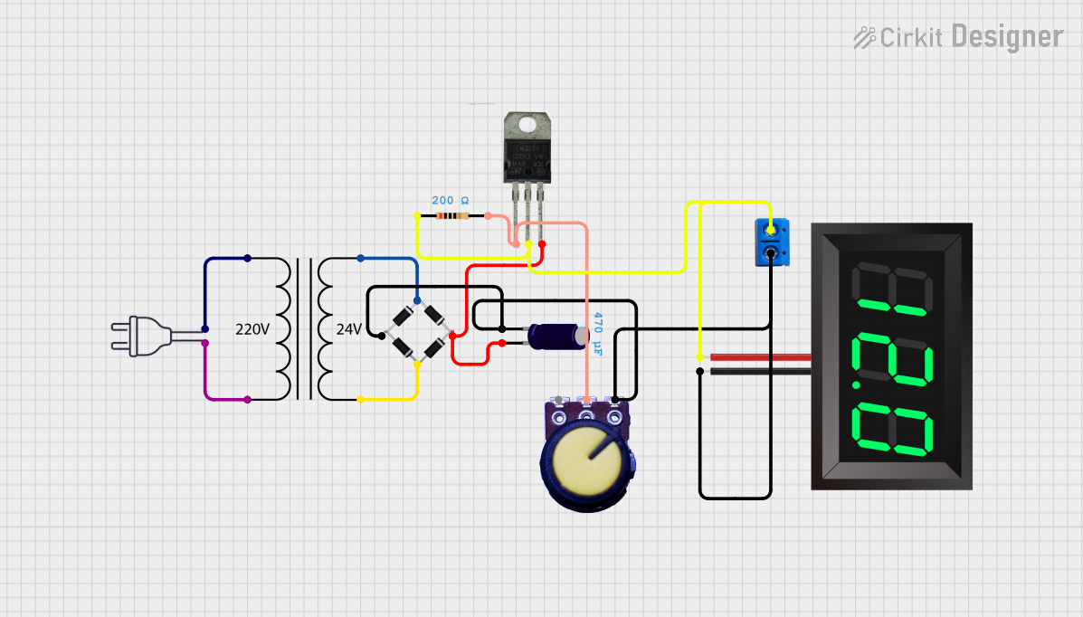
Circuit Diagram
- LV → 3.3V power supply
- HV → Arduino UNO 5V pin
- GND → Common ground
- LV1 → Sensor's data pin
- HV1 → Arduino UNO digital pin 2
Arduino Code Example
// Example: Reading data from a 3.3V sensor using a level converter
// Connect the sensor's data pin to LV1 and Arduino pin 2 to HV1

const int sensorPin = 2; // Arduino pin connected to HV1

void setup() {
  Serial.begin(9600); // Initialize serial communication
  pinMode(sensorPin, INPUT); // Set pin as input
}

void loop() {
  int sensorValue = digitalRead(sensorPin); // Read sensor value
  Serial.println(sensorValue); // Print the value to the Serial Monitor
  delay(500); // Wait for 500ms before the next reading
}
Troubleshooting and FAQs
Common Issues and Solutions
No Signal Translation:
- Cause: Incorrect power supply connections.
- Solution: Verify that the LV and HV pins are connected to the correct voltage levels.
Signal Distortion or Noise:
- Cause: Long wires or improper grounding.
- Solution: Use shorter wires and ensure a solid ground connection.
I2C Communication Fails:
- Cause: Missing pull-up resistors.
- Solution: Add pull-up resistors (typically 4.7kΩ) to the SDA and SCL lines.
Overheating:
- Cause: Exceeding the maximum current rating.
- Solution: Ensure that the current per channel does not exceed 50mA.
FAQs
Q1: Can I use the Level Converter for unidirectional signals?
Yes, the Level Converter works for both unidirectional and bidirectional signals.
Q2: Can I use this component for analog signals?
No, the Level Converter is designed for digital signals only.
Q3: What happens if I connect the wrong voltage to the LV or HV pins?
Connecting incorrect voltages may damage the component or connected devices. Always double-check your connections.
Q4: Can I use this Level Converter with a 1.8V device?
Yes, the Level Converter supports low-voltage devices down to 1.8V on the LV side.