How to Use Super-bright YELLOW LED module: Examples, Pinouts, and Specs
Introduction
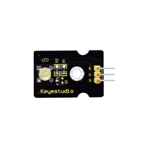
The Super-bright YELLOW LED Module (Manufacturer: Keyestudio, Part ID: KS0234) is a high-intensity yellow light-emitting diode (LED) module designed for bright illumination. It is ideal for applications such as displays, status indicators, decorative lighting, and educational projects. The module is easy to integrate into circuits and is compatible with microcontrollers like Arduino, making it suitable for both beginners and advanced users.
Explore Projects Built with Super-bright YELLOW LED module


Explore Projects Built with Super-bright YELLOW LED module
Common Applications
- Status indicators in electronic devices
- Decorative and ambient lighting
- Educational and prototyping projects
- Signal and display systems
- DIY electronics and hobbyist projects
Technical Specifications
Below are the key technical details of the Super-bright YELLOW LED Module:
| Parameter | Specification |
|---|---|
| Operating Voltage | 3.3V to 5V |
| Forward Current | 20mA (typical) |
| LED Color | Yellow |
| Wavelength | 590-595 nm |
| Brightness | Super-bright |
| Dimensions | 22mm x 18mm x 8mm |
| Mounting Type | PCB-mounted |
| Operating Temperature | -25°C to 85°C |
Pin Configuration
The module has three pins, as described in the table below:
| Pin | Name | Description |
|---|---|---|
| 1 | Signal (S) | Input pin to control the LED (connect to microcontroller GPIO) |
| 2 | VCC | Power supply pin (3.3V or 5V) |
| 3 | GND | Ground connection |
Usage Instructions
How to Use the Module in a Circuit
- Power Supply: Connect the VCC pin to a 3.3V or 5V power source, depending on your circuit's requirements.
- Ground Connection: Connect the GND pin to the ground of your circuit.
- Signal Control: Use the Signal (S) pin to control the LED. This pin can be connected to a GPIO pin of a microcontroller (e.g., Arduino) or directly to a power source for constant illumination.
- Current Limiting Resistor: If not already included on the module, use a 220Ω or 330Ω resistor in series with the Signal pin to limit the current and protect the LED.
Important Considerations
- Polarity: Ensure correct polarity when connecting the module. Reversing the VCC and GND pins can damage the module.
- Current Limiting: Always use a current-limiting resistor if the module does not have one built-in.
- Brightness Control: Use PWM (Pulse Width Modulation) on the Signal pin to adjust the brightness of the LED.
- Heat Management: Avoid prolonged operation at maximum brightness to prevent overheating.
Example: Connecting to an Arduino UNO
Below is an example of how to connect and control the Super-bright YELLOW LED Module using an Arduino UNO:
Circuit Diagram
- Connect the Signal (S) pin of the module to Arduino digital pin 9.
- Connect the VCC pin to the 5V pin on the Arduino.
- Connect the GND pin to the GND pin on the Arduino.
Arduino Code
// Super-bright YELLOW LED Module Example
// Manufacturer: Keyestudio
// Part ID: KS0234

// Define the pin connected to the LED module
const int ledPin = 9;

void setup() {
  // Set the LED pin as an output
  pinMode(ledPin, OUTPUT);
}

void loop() {
  // Turn the LED on
  digitalWrite(ledPin, HIGH);
  delay(1000); // Keep the LED on for 1 second

  // Turn the LED off
  digitalWrite(ledPin, LOW);
  delay(1000); // Keep the LED off for 1 second
}
Notes
- The above code creates a simple blinking effect for the LED.
- To adjust brightness, replace
digitalWritewithanalogWriteand provide a PWM value (0-255).
Troubleshooting and FAQs
Common Issues
LED Does Not Light Up
- Cause: Incorrect wiring or reversed polarity.
- Solution: Double-check the connections and ensure the VCC, GND, and Signal pins are correctly connected.
LED Flickers or Is Dim
- Cause: Insufficient power supply or missing current-limiting resistor.
- Solution: Ensure the power supply provides sufficient voltage and current. Add a resistor if necessary.
Module Overheats
- Cause: Prolonged operation at maximum brightness or excessive current.
- Solution: Use PWM to reduce brightness or add a heat sink if required.
Arduino Code Does Not Work
- Cause: Incorrect pin configuration or syntax errors in the code.
- Solution: Verify the pin number in the code matches the physical connection. Check for typos in the code.
FAQs
Q: Can I use this module with a 3.3V microcontroller?
A: Yes, the module is compatible with both 3.3V and 5V systems.
Q: Does the module include a built-in resistor?
A: Some versions of the module may include a built-in resistor. Check the product documentation or visually inspect the module to confirm.
Q: How can I adjust the brightness of the LED?
A: Use PWM (Pulse Width Modulation) on the Signal pin to control the brightness. For Arduino, use the analogWrite() function.
Q: Can I use this module outdoors?
A: The module is not waterproof. If outdoor use is required, ensure proper waterproofing measures are taken.
This concludes the documentation for the Super-bright YELLOW LED Module (KS0234). For further assistance, refer to the Keyestudio support resources.