How to Use Power Inverter: Examples, Pinouts, and Specs
Introduction
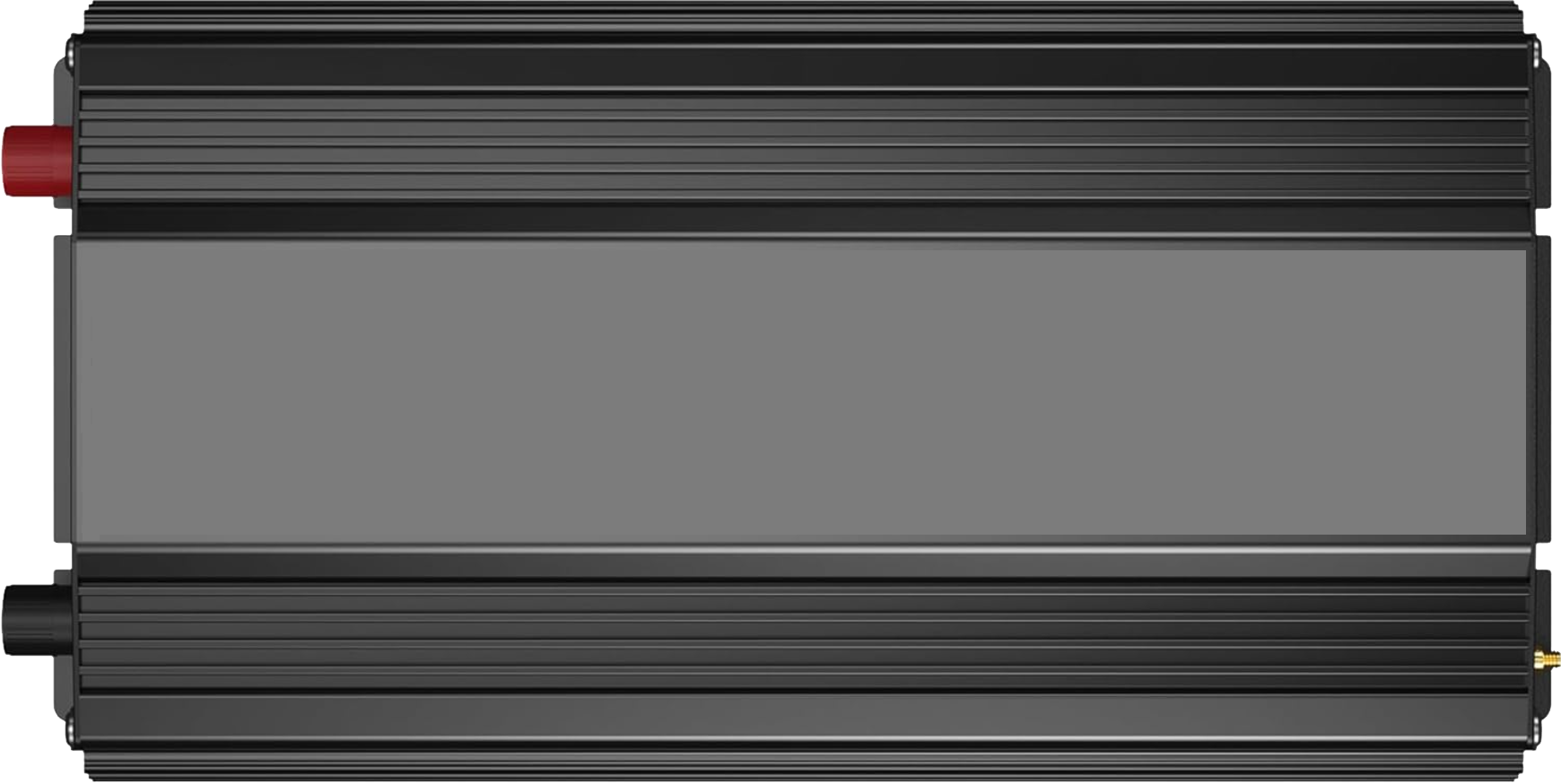
The VOLTWORKS Store ETL UL458 12V DC to 110V 120V AC 1000W Power Inverter is a high-performance electronic device designed to convert direct current (DC) from a 12V battery into alternating current (AC) at 110V or 120V. This allows DC power sources, such as car batteries or solar panels, to power standard AC devices like laptops, small appliances, and other household electronics.
Explore Projects Built with Power Inverter
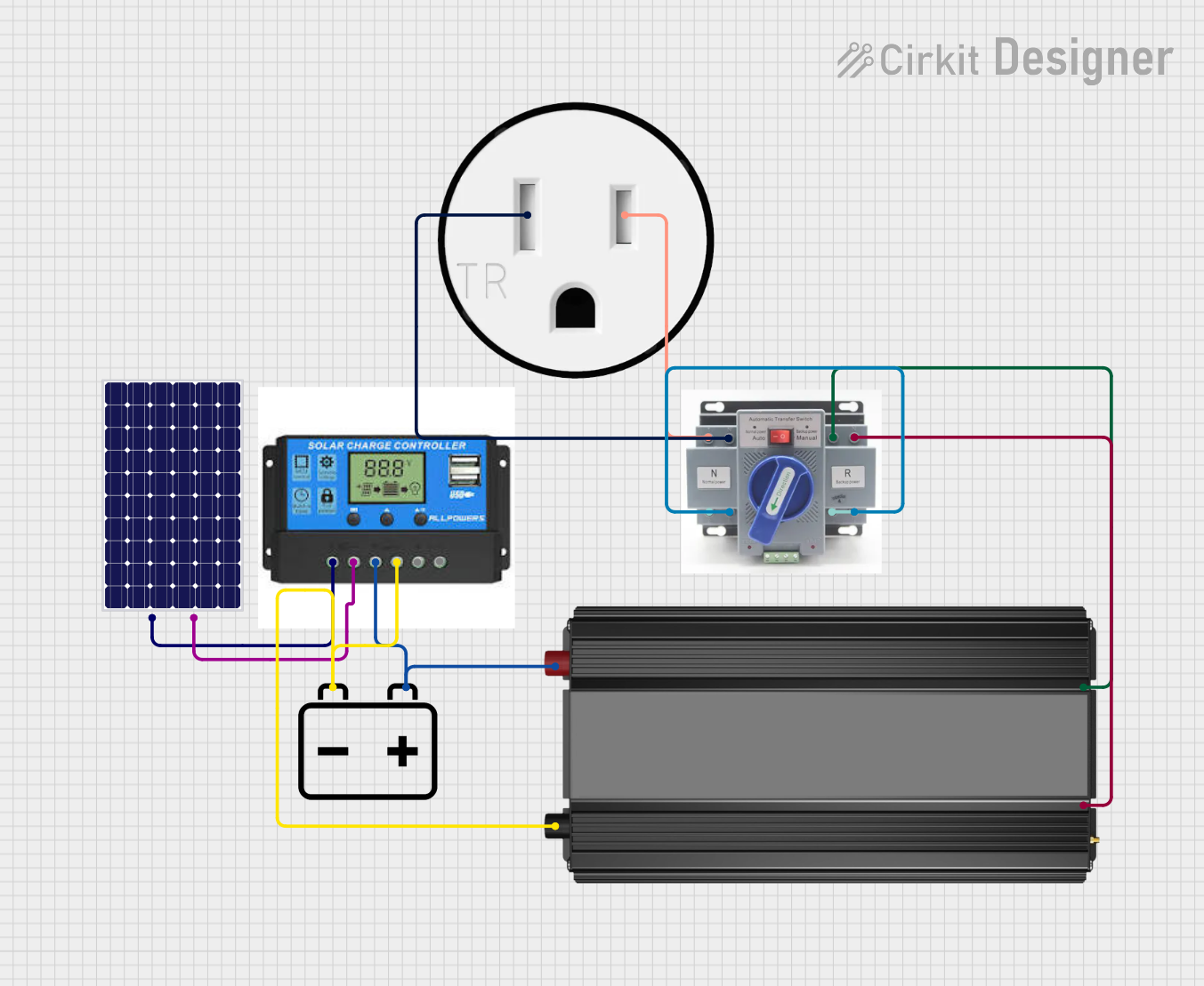

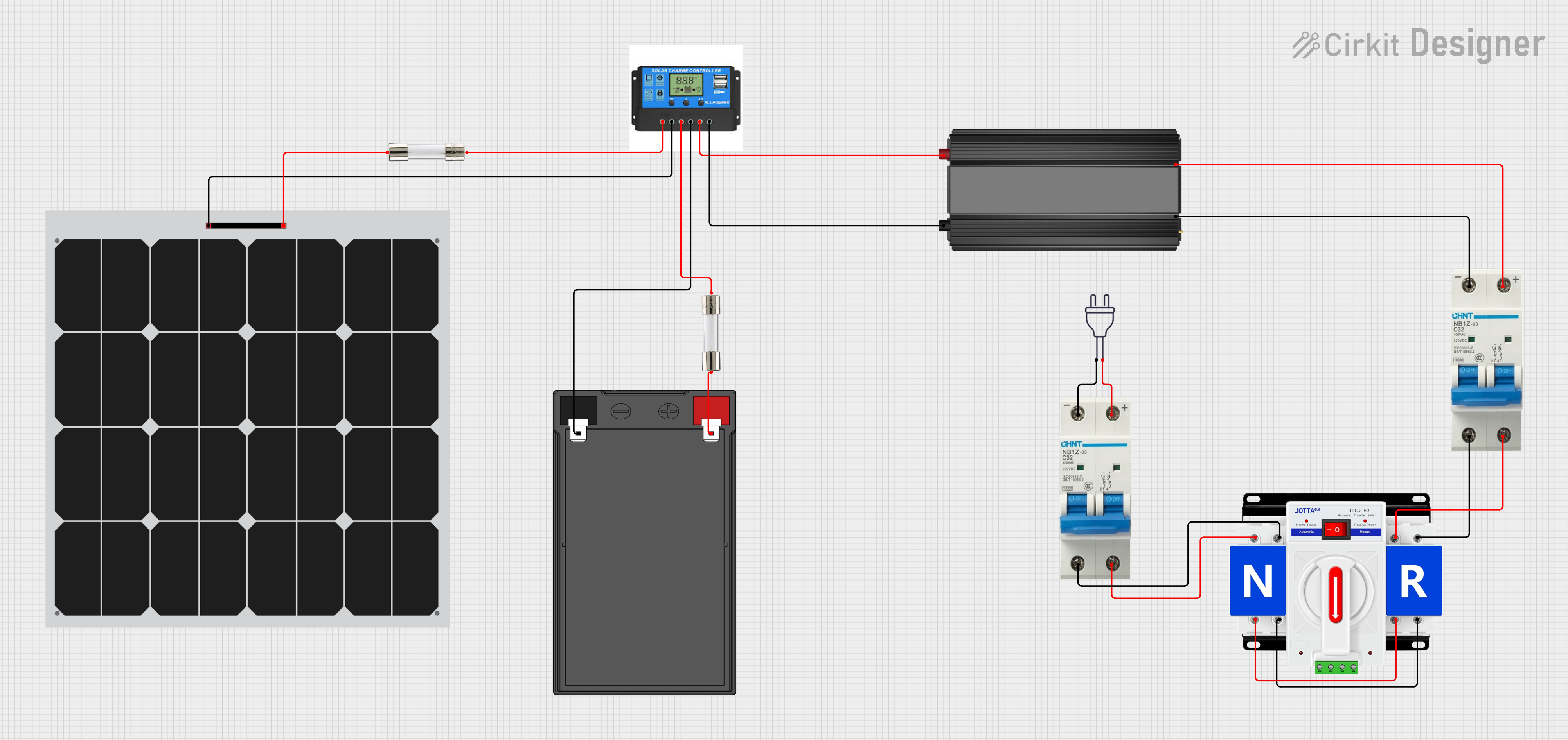
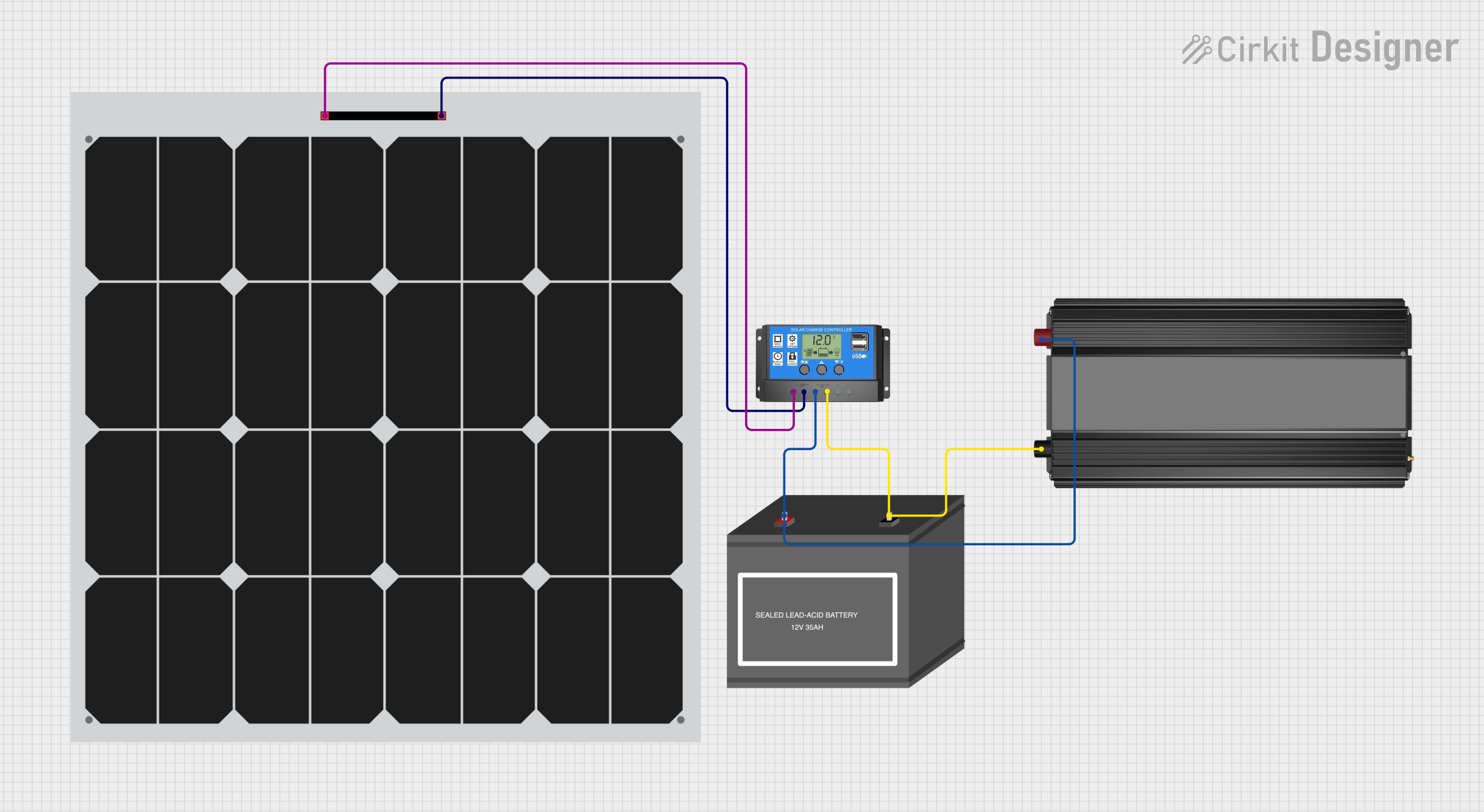
Explore Projects Built with Power Inverter
Common Applications and Use Cases
- Powering household appliances during off-grid or emergency situations.
- Running AC devices in vehicles, RVs, or boats.
- Supporting renewable energy systems, such as solar or wind setups.
- Providing backup power for sensitive electronics during outages.
Technical Specifications
Below are the key technical details for the ETL UL458 12V DC to 110V 120V AC 1000W Power Inverter:
| Specification | Details |
|---|---|
| Input Voltage | 12V DC |
| Output Voltage | 110V/120V AC |
| Continuous Power Output | 1000W |
| Peak Power Output | 2000W |
| Output Waveform | Modified Sine Wave |
| Efficiency | ≥90% |
| Input Voltage Range | 10.5V - 15.5V DC |
| Output Frequency | 60Hz ± 2Hz |
| Protection Features | Overload, over-voltage, under-voltage, over-temperature, and short-circuit |
| Cooling System | Intelligent temperature-controlled fan |
| Dimensions | 10.5 x 6.5 x 2.5 inches |
| Weight | 4.4 lbs (2 kg) |
Pin Configuration and Descriptions
The power inverter has the following key input/output connections:
| Pin/Port | Description |
|---|---|
| DC Input Terminals | Connect to a 12V DC battery (positive and negative terminals). |
| AC Output Sockets | Standard 110V/120V AC outlets for connecting appliances. |
| USB Ports | USB output ports for charging small devices (e.g., phones, tablets). |
| Ground Terminal | Provides grounding for safety and reduces electrical noise. |
| Cooling Fan | Automatically activates to prevent overheating during operation. |
| Power Switch | Turns the inverter on or off. |
| LED Indicators | Displays operational status (e.g., power, fault, or protection mode). |
Usage Instructions
How to Use the Power Inverter in a Circuit
Connect the Inverter to a DC Power Source:
- Ensure the DC power source (e.g., a 12V battery) is fully charged.
- Connect the positive (red) and negative (black) terminals of the inverter to the corresponding terminals of the battery using the provided cables.
- Tighten the connections securely to avoid loose contacts.
Connect AC Devices:
- Plug your AC devices into the inverter's AC output sockets.
- Ensure the total power consumption of connected devices does not exceed the inverter's 1000W continuous power rating.
Turn On the Inverter:
- Flip the power switch to the "ON" position.
- Verify that the LED indicators show normal operation (e.g., green light for power).
Monitor Operation:
- The inverter will automatically regulate the output voltage and frequency.
- If the inverter enters protection mode (e.g., due to overload or low battery), disconnect all devices and resolve the issue before restarting.
Important Considerations and Best Practices
- Battery Capacity: Use a battery with sufficient capacity to support the power requirements of your devices. For example, a 100Ah battery can provide approximately 1 hour of runtime at 1000W.
- Ventilation: Place the inverter in a well-ventilated area to prevent overheating. Avoid enclosing it in tight spaces.
- Grounding: Always connect the ground terminal to a proper earth ground to ensure safety.
- Device Compatibility: This inverter produces a modified sine wave output, which may not be suitable for sensitive electronics like medical equipment or certain audio devices. Check device specifications before use.
- Avoid Overloading: Do not exceed the 1000W continuous power rating or the 2000W peak power rating.
Example: Connecting the Inverter to an Arduino UNO
If you are using the inverter to power an Arduino UNO and other peripherals, follow these steps:
- Connect the inverter to a 12V battery as described above.
- Plug a 5V USB adapter into one of the inverter's AC outlets.
- Use the USB adapter to power the Arduino UNO via its USB port.
Here is a simple Arduino code example to blink an LED while powered by the inverter:
// Simple LED Blink Code for Arduino UNO
// This code blinks an LED connected to pin 13 every second.

void setup() {
  pinMode(13, OUTPUT); // Set pin 13 as an output pin
}

void loop() {
  digitalWrite(13, HIGH); // Turn the LED on
  delay(1000);            // Wait for 1 second
  digitalWrite(13, LOW);  // Turn the LED off
  delay(1000);            // Wait for 1 second
}
Troubleshooting and FAQs
Common Issues and Solutions
| Issue | Possible Cause | Solution |
|---|---|---|
| Inverter does not turn on | Battery voltage is too low or connections are loose. | Check battery voltage and ensure secure connections. |
| Devices do not power on | Overload or incompatible device. | Ensure total load is within 1000W and check device compatibility. |
| Inverter shuts down unexpectedly | Over-temperature or low battery voltage. | Allow the inverter to cool down and recharge the battery. |
| LED shows fault indicator | Protection mode activated (e.g., short circuit). | Disconnect all devices, resolve the issue, and restart the inverter. |
| Excessive noise from connected devices | Modified sine wave output is incompatible. | Use a pure sine wave inverter for sensitive electronics. |
FAQs
Can I use this inverter with a solar panel?
- Yes, but you will need a charge controller to regulate the solar panel's output and charge the battery.
What happens if I exceed the 1000W power limit?
- The inverter will enter protection mode and shut down to prevent damage. Reduce the load and restart the inverter.
Is this inverter safe for laptops and phones?
- Yes, most laptops and phones are compatible with modified sine wave inverters. However, check your device's specifications to confirm.
Can I connect this inverter directly to a car's cigarette lighter socket?
- No, the inverter requires a direct connection to the battery terminals for proper operation at high power levels.
By following this documentation, you can safely and effectively use the VOLTWORKS Store ETL UL458 12V DC to 110V 120V AC 1000W Power Inverter for a variety of applications.