How to Use Adapter mit AMS1117 für NRF24L01 Wireless RF Transceiver Modul 2,4 GHz mit 8Pins: Examples, Pinouts, and Specs
Introduction
The AZDelivery NRF24L01 Adapter with AMS1117 is a versatile adapter module designed to facilitate the use of the NRF24L01 2.4 GHz wireless RF transceiver module. This adapter features the AMS1117 voltage regulator, which ensures stable voltage regulation, making it ideal for various wireless communication projects. The module comes with 8 pins for easy connectivity and integration into your circuits.
Explore Projects Built with Adapter mit AMS1117 für NRF24L01 Wireless RF Transceiver Modul 2,4 GHz mit 8Pins

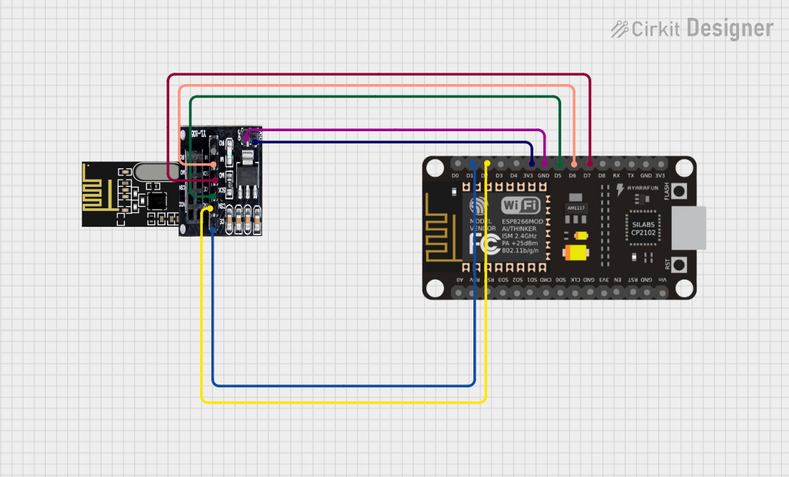
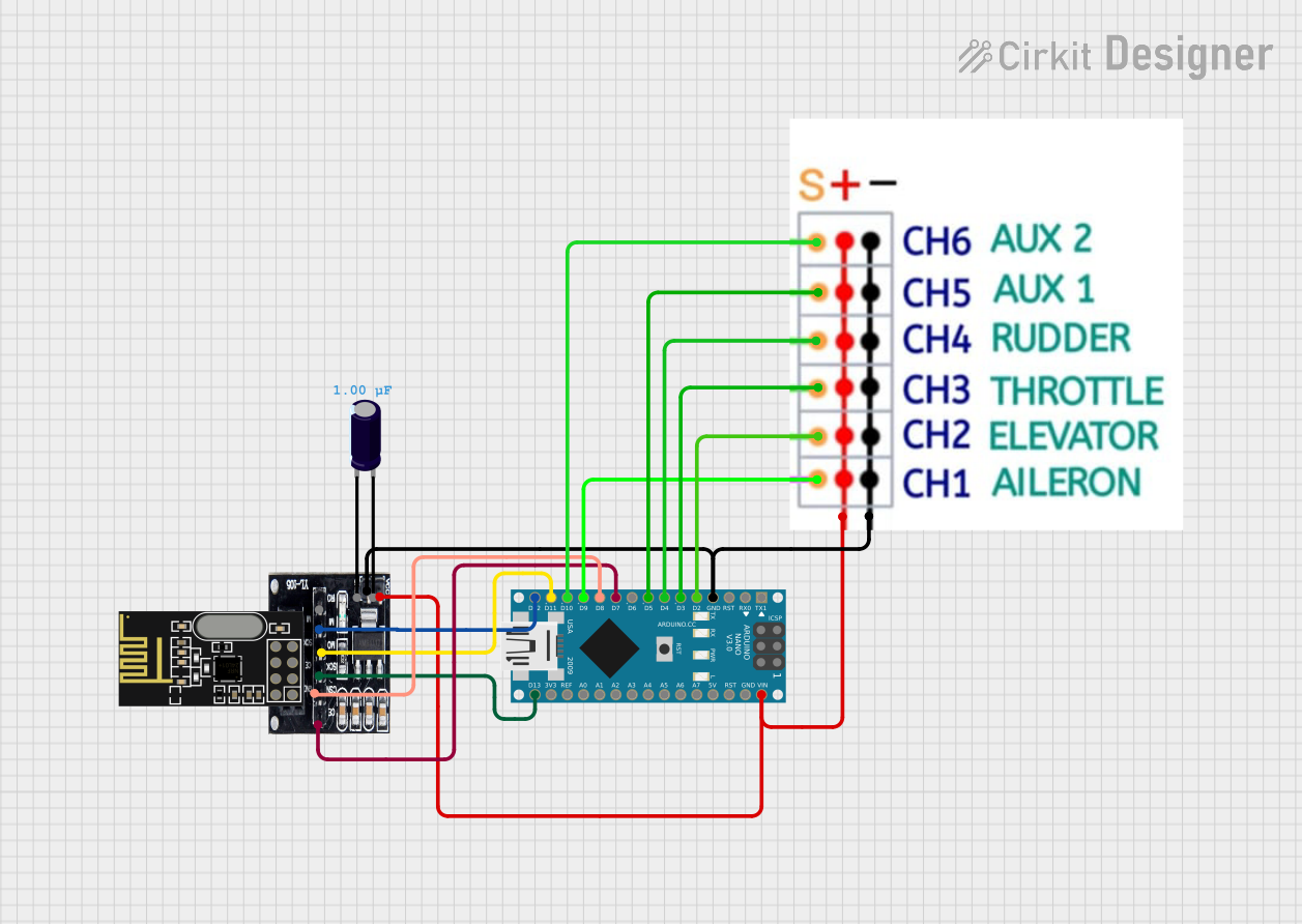
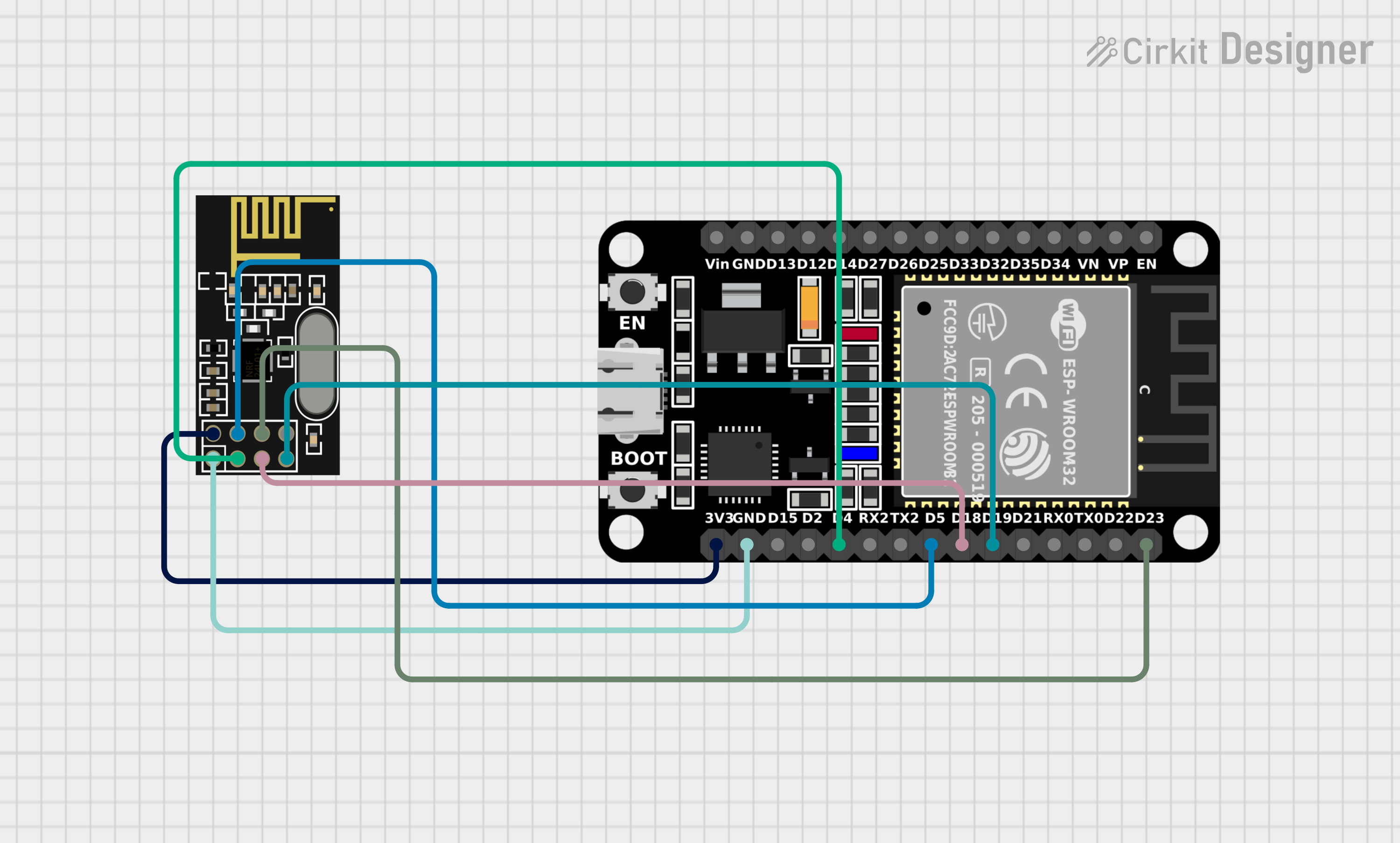
Explore Projects Built with Adapter mit AMS1117 für NRF24L01 Wireless RF Transceiver Modul 2,4 GHz mit 8Pins
Common Applications and Use Cases
- Wireless Communication: Ideal for creating wireless communication links between microcontrollers.
- IoT Projects: Suitable for Internet of Things (IoT) applications requiring reliable wireless data transmission.
- Remote Control Systems: Can be used in remote control systems for home automation, robotics, and more.
- Sensor Networks: Perfect for setting up wireless sensor networks for data collection and monitoring.
Technical Specifications
Key Technical Details
| Parameter | Value |
|---|---|
| Voltage Input | 3.3V - 5V |
| Voltage Output | 3.3V |
| Current Output | 800mA (max) |
| Frequency | 2.4 GHz |
| Number of Pins | 8 |
| Regulator Type | AMS1117 |
| Operating Temperature | -40°C to 85°C |
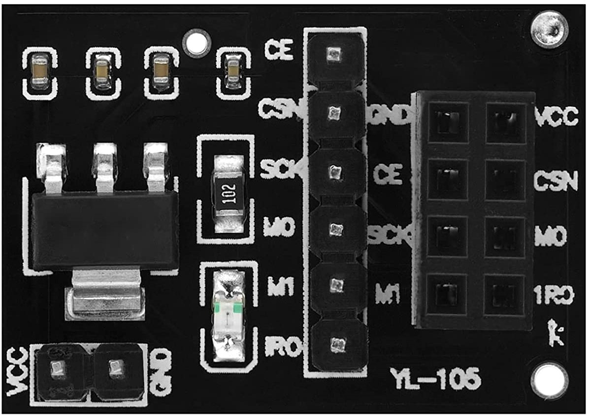
Pin Configuration and Descriptions
| Pin Number | Pin Name | Description |
|---|---|---|
| 1 | GND | Ground |
| 2 | VCC | Power Supply (3.3V) |
| 3 | CE | Chip Enable |
| 4 | CSN | Chip Select Not |
| 5 | SCK | Serial Clock |
| 6 | MOSI | Master Out Slave In |
| 7 | MISO | Master In Slave Out |
| 8 | IRQ | Interrupt Request |
Usage Instructions
How to Use the Component in a Circuit
- Power Supply: Connect the VCC pin to a 3.3V power source. The AMS1117 regulator will ensure stable voltage for the NRF24L01 module.
- Ground Connection: Connect the GND pin to the ground of your circuit.
- SPI Interface: Connect the CE, CSN, SCK, MOSI, and MISO pins to the corresponding pins on your microcontroller.
- Interrupt Pin: Optionally, connect the IRQ pin to an interrupt-capable pin on your microcontroller for handling interrupts.
Important Considerations and Best Practices
- Voltage Levels: Ensure that the VCC pin is connected to a 3.3V power source. The NRF24L01 module is sensitive to higher voltages and may get damaged if supplied with more than 3.3V.
- Decoupling Capacitors: Use decoupling capacitors close to the VCC and GND pins to filter out noise and ensure stable operation.
- Antenna Placement: For optimal wireless performance, place the NRF24L01 module away from metal objects and other sources of interference.
Example Code for Arduino UNO
#include <SPI.h>
#include <nRF24L01.h>
#include <RF24.h>

// Create an RF24 object
RF24 radio(9, 10); // CE pin 9, CSN pin 10

// Address for communication
const byte address[6] = "00001";

void setup() {
  Serial.begin(9600);
  radio.begin();
  radio.openWritingPipe(address);
  radio.setPALevel(RF24_PA_MIN);
  radio.stopListening();
}

void loop() {
  const char text[] = "Hello World";
  radio.write(&text, sizeof(text));
  Serial.println("Sent: Hello World");
  delay(1000);
}
Troubleshooting and FAQs
Common Issues Users Might Face
No Communication Between Modules:
- Solution: Ensure that both modules are powered correctly and that the SPI connections are secure. Verify that the addresses match on both the transmitter and receiver.
Unstable Operation:
- Solution: Check for proper power supply and use decoupling capacitors. Ensure that the antenna is placed correctly and away from interference sources.
Module Not Responding:
- Solution: Verify the voltage levels and ensure that the VCC pin is supplied with 3.3V. Check the connections and ensure that the CE and CSN pins are correctly connected to the microcontroller.
FAQs
Q: Can I use a 5V power supply with this adapter?
- A: Yes, the AMS1117 regulator will step down the voltage to 3.3V for the NRF24L01 module.
Q: What is the maximum range of the NRF24L01 module?
- A: The range can vary depending on the environment, but typically it can reach up to 100 meters in open space.
Q: Do I need to use the IRQ pin?
- A: The IRQ pin is optional and is used for handling interrupts. It is not required for basic communication.
This documentation provides a comprehensive guide to using the AZDelivery NRF24L01 Adapter with AMS1117. Whether you are a beginner or an experienced user, this guide will help you integrate this component into your projects effectively.