How to Use SCC: Examples, Pinouts, and Specs
Introduction
- A Switching Converter Controller (SCC) is a device designed to regulate the output voltage of a switching power supply. It achieves this by controlling the duty cycle of the switching elements, ensuring efficient power conversion and stable output.
- Common applications of SCCs include:
- DC-DC converters (e.g., buck, boost, or buck-boost converters)
- Power management in battery-operated devices
- Voltage regulation in industrial and automotive systems
- Renewable energy systems, such as solar inverters
Explore Projects Built with SCC
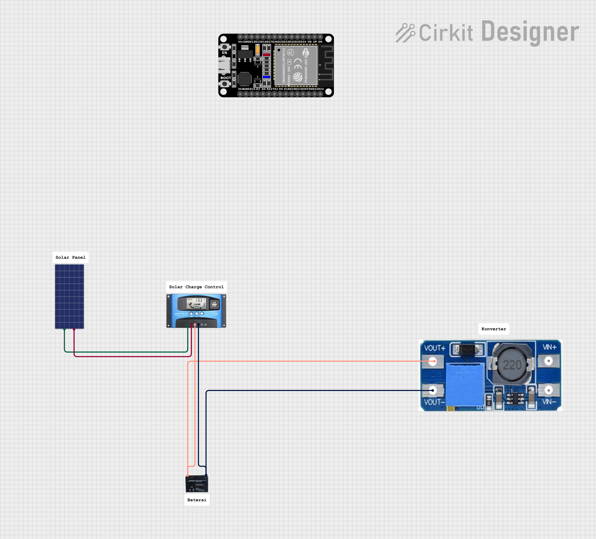
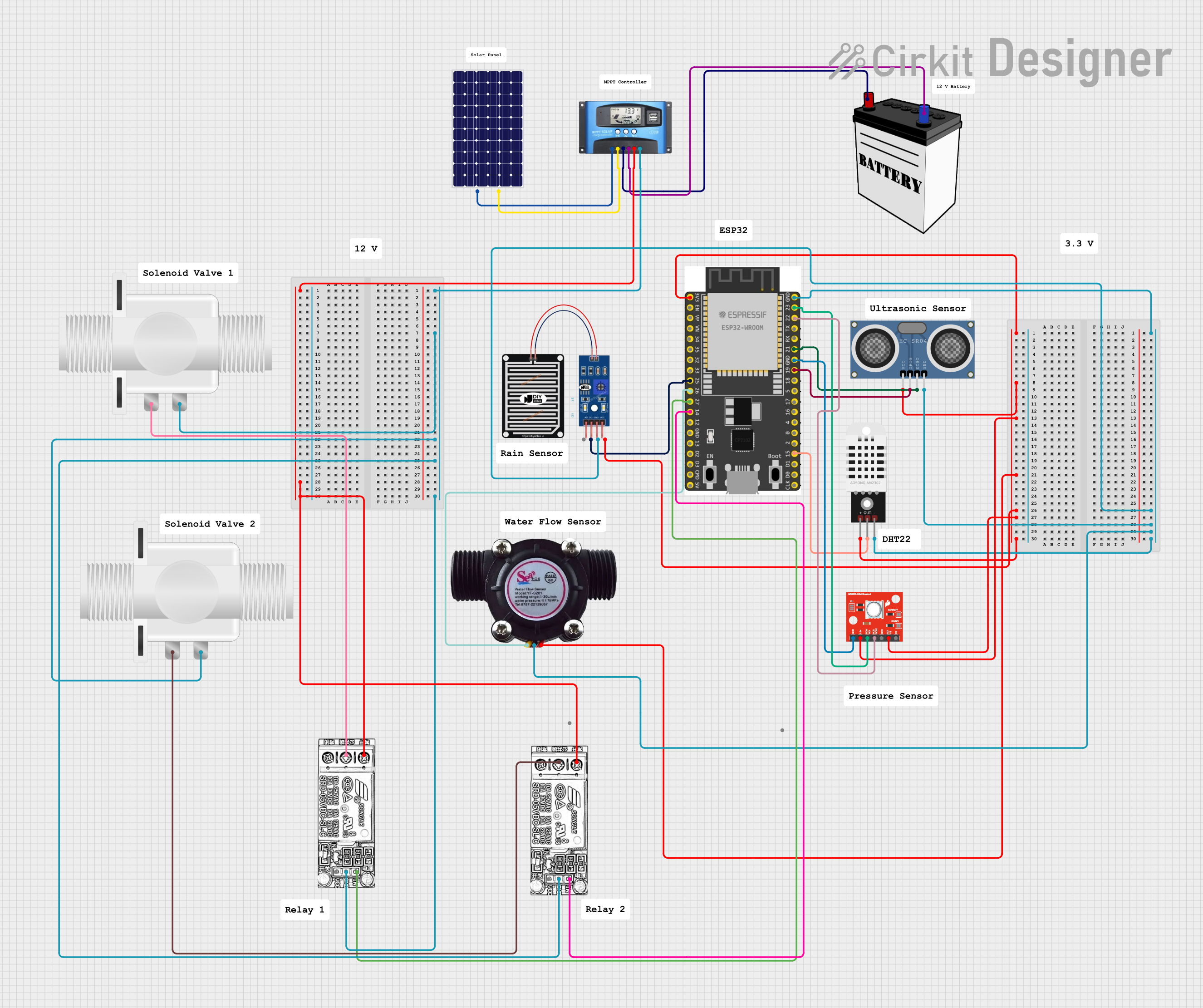
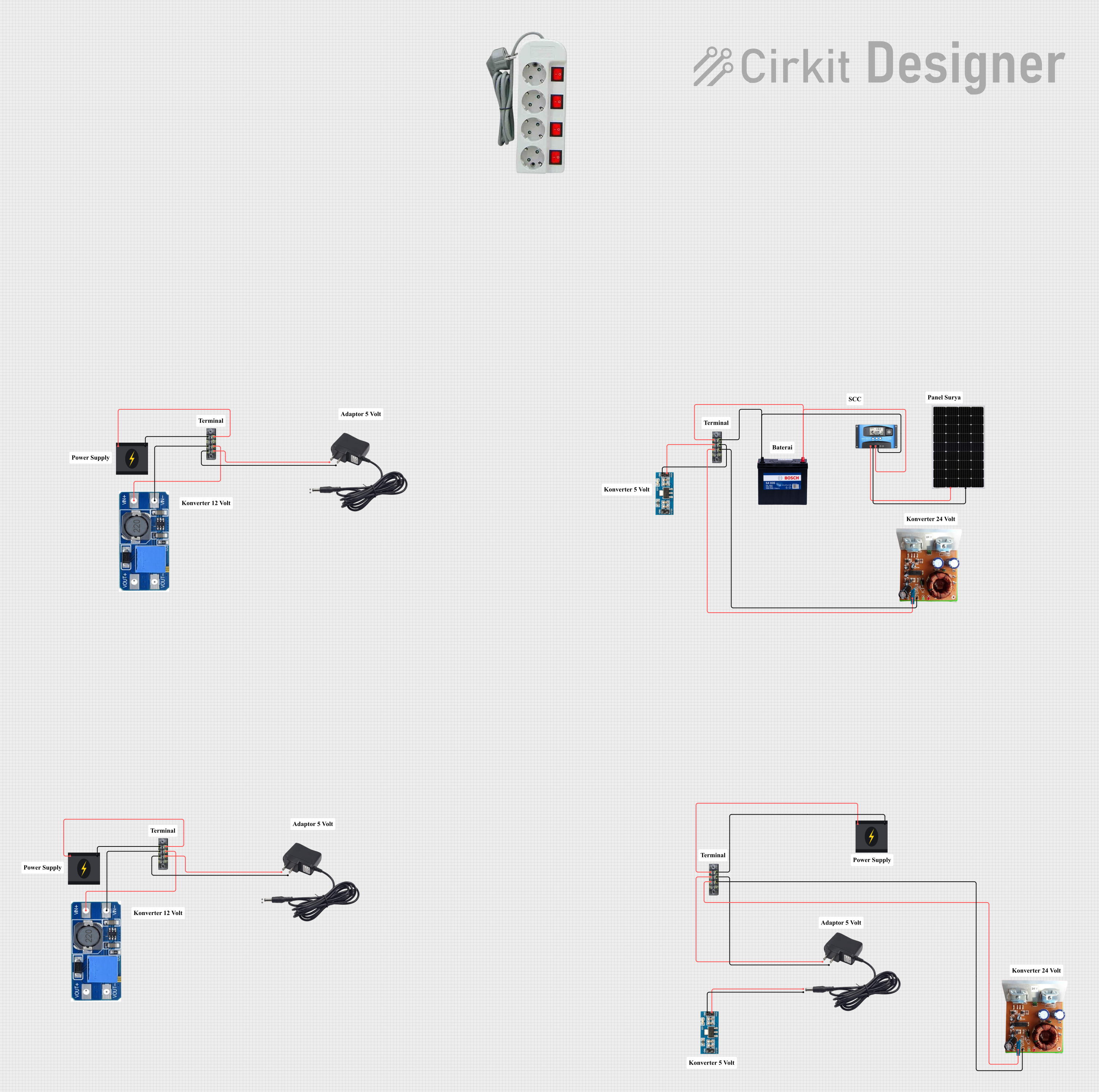

Explore Projects Built with SCC
Technical Specifications
- Below are the key technical details for a typical SCC:
- Input Voltage Range: 4.5V to 40V
- Output Voltage Range: Adjustable (e.g., 0.8V to 30V, depending on feedback configuration)
- Switching Frequency: 100 kHz to 2 MHz (varies by model)
- Efficiency: Up to 95% (depending on load and configuration)
- Operating Temperature: -40°C to +125°C
- Control Method: Pulse Width Modulation (PWM)
- Protection Features: Overcurrent protection (OCP), thermal shutdown, undervoltage lockout (UVLO)
Pin Configuration and Descriptions
The SCC typically comes in an 8-pin or 16-pin package. Below is an example of an 8-pin configuration:
| Pin Number | Pin Name | Description |
|---|---|---|
| 1 | VIN | Input voltage pin. Connects to the input power supply. |
| 2 | GND | Ground pin. Connects to the system ground. |
| 3 | FB | Feedback pin. Used to sense the output voltage for regulation. |
| 4 | COMP | Compensation pin. Connects to external components for loop stability. |
| 5 | EN | Enable pin. Used to turn the SCC on or off. |
| 6 | SW | Switch pin. Connects to the switching element (e.g., MOSFET). |
| 7 | BOOT | Bootstrap pin. Provides the gate drive voltage for the high-side MOSFET. |
| 8 | RT/CLK | Resistor timing or clock input pin. Sets the switching frequency. |
Usage Instructions
How to Use the SCC in a Circuit
Input and Output Connections:
- Connect the input voltage source to the VIN pin.
- Connect the load to the output of the power supply circuit.
- Use appropriate decoupling capacitors near the VIN and GND pins to reduce noise.
Feedback Configuration:
- Use a resistor divider network to connect the output voltage to the FB pin.
- Select resistor values to set the desired output voltage using the formula: [ V_{OUT} = V_{REF} \times \left(1 + \frac{R_1}{R_2}\right) ] where ( V_{REF} ) is the reference voltage (typically 0.8V).
Switching Frequency:
- Connect a resistor to the RT/CLK pin to set the switching frequency.
- Refer to the SCC datasheet for the resistor value corresponding to the desired frequency.
Enable Pin:
- Pull the EN pin high to enable the SCC.
- Pull it low to disable the SCC and reduce power consumption.
Bootstrap Capacitor:
- Connect a bootstrap capacitor (e.g., 0.1 µF) between the BOOT and SW pins to drive the high-side MOSFET.
Important Considerations and Best Practices
- Thermal Management: Ensure proper heat dissipation by using a heatsink or placing the SCC on a PCB with good thermal conductivity.
- Inductor Selection: Choose an inductor with appropriate current rating and low DC resistance to minimize losses.
- Capacitor Selection: Use low-ESR capacitors for input and output filtering to reduce ripple.
- PCB Layout: Minimize the length of high-current paths and place decoupling capacitors close to the SCC pins.
Example: Using SCC with Arduino UNO
Below is an example of controlling the SCC's enable pin using an Arduino UNO:
// Define the pin connected to the SCC's EN pin
const int enablePin = 7;

void setup() {
  // Set the enable pin as an output
  pinMode(enablePin, OUTPUT);

  // Enable the SCC by setting the pin HIGH
  digitalWrite(enablePin, HIGH);
}

void loop() {
  // Example: Toggle the SCC on and off every 5 seconds
  digitalWrite(enablePin, HIGH); // Enable SCC
  delay(5000);                   // Wait for 5 seconds
  digitalWrite(enablePin, LOW);  // Disable SCC
  delay(5000);                   // Wait for 5 seconds
}
Troubleshooting and FAQs
Common Issues and Solutions
Output Voltage is Incorrect:
- Cause: Incorrect feedback resistor values.
- Solution: Verify the resistor divider network and recalculate the values.
SCC Overheats:
- Cause: Insufficient cooling or excessive load current.
- Solution: Improve thermal management (e.g., add a heatsink) and ensure the load is within the SCC's current rating.
No Output Voltage:
- Cause: EN pin is not pulled high or input voltage is too low.
- Solution: Check the EN pin voltage and ensure the input voltage is within the specified range.
High Output Ripple:
- Cause: Poor capacitor selection or layout issues.
- Solution: Use low-ESR capacitors and optimize PCB layout to reduce noise.
FAQs
Q: Can the SCC be used for both step-up and step-down applications?
A: Yes, depending on the circuit configuration, the SCC can be used in buck (step-down), boost (step-up), or buck-boost converters.Q: How do I calculate the switching frequency?
A: Refer to the SCC datasheet for the formula or resistor value required to set the desired frequency.Q: What happens if the input voltage drops below the specified range?
A: The SCC may enter undervoltage lockout (UVLO) mode to protect the circuit.Q: Can I use the SCC with a battery-powered system?
A: Yes, SCCs are commonly used in battery-powered systems for efficient power management.
This concludes the documentation for the Switching Converter Controller (SCC).