How to Use Adafruit 9-DOF : Examples, Pinouts, and Specs
Introduction
The Adafruit 9-DOF sensor module is a versatile and compact device that integrates three essential motion and orientation sensors: a 3-axis accelerometer, a 3-axis gyroscope, and a 3-axis magnetometer. This combination allows the module to measure linear acceleration, angular velocity, and magnetic field strength in three dimensions, making it ideal for applications requiring precise motion tracking and orientation sensing.
Explore Projects Built with Adafruit 9-DOF


Explore Projects Built with Adafruit 9-DOF
Common Applications and Use Cases
- Robotics and drone navigation
- Gesture recognition and motion tracking
- Virtual reality (VR) and augmented reality (AR) systems
- Inertial measurement units (IMUs) for scientific experiments
- Wearable devices and fitness trackers
Technical Specifications
The Adafruit 9-DOF sensor module is built around the LSM9DS1 chip, which integrates the accelerometer, gyroscope, and magnetometer. Below are the key technical details:
Key Technical Details
- Supply Voltage: 3.3V to 5V
- Communication Protocols: I²C (default) or SPI
- Accelerometer Range: ±2g, ±4g, ±8g, ±16g
- Gyroscope Range: ±245°/s, ±500°/s, ±2000°/s
- Magnetometer Range: ±4 gauss, ±8 gauss, ±12 gauss, ±16 gauss
- Operating Temperature Range: -40°C to +85°C
- Dimensions: 20mm x 20mm x 3mm
- Weight: ~1.5g
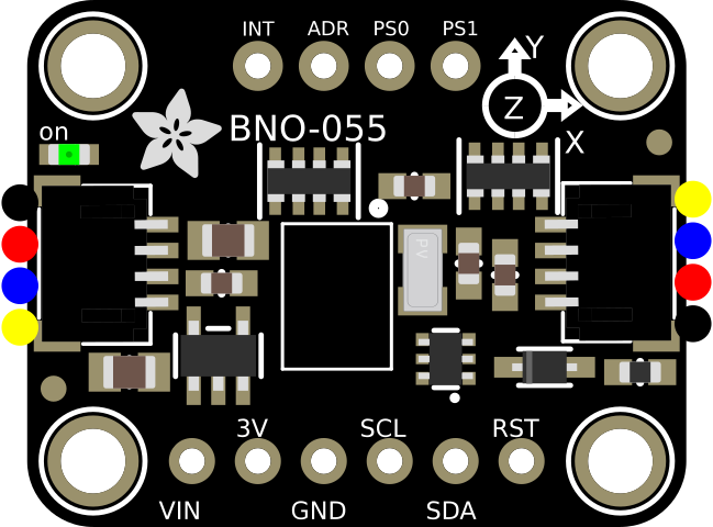
Pin Configuration and Descriptions
The Adafruit 9-DOF module has the following pin layout:
| Pin Name | Description |
|---|---|
| VIN | Power input (3.3V to 5V) |
| GND | Ground connection |
| SCL | I²C clock line (or SPI clock line in SPI mode) |
| SDA | I²C data line (or SPI MOSI line in SPI mode) |
| CS | Chip select for SPI communication (leave unconnected for I²C mode) |
| INT1 | Interrupt 1 output (can be configured for various sensor events) |
| INT2 | Interrupt 2 output (can be configured for various sensor events) |
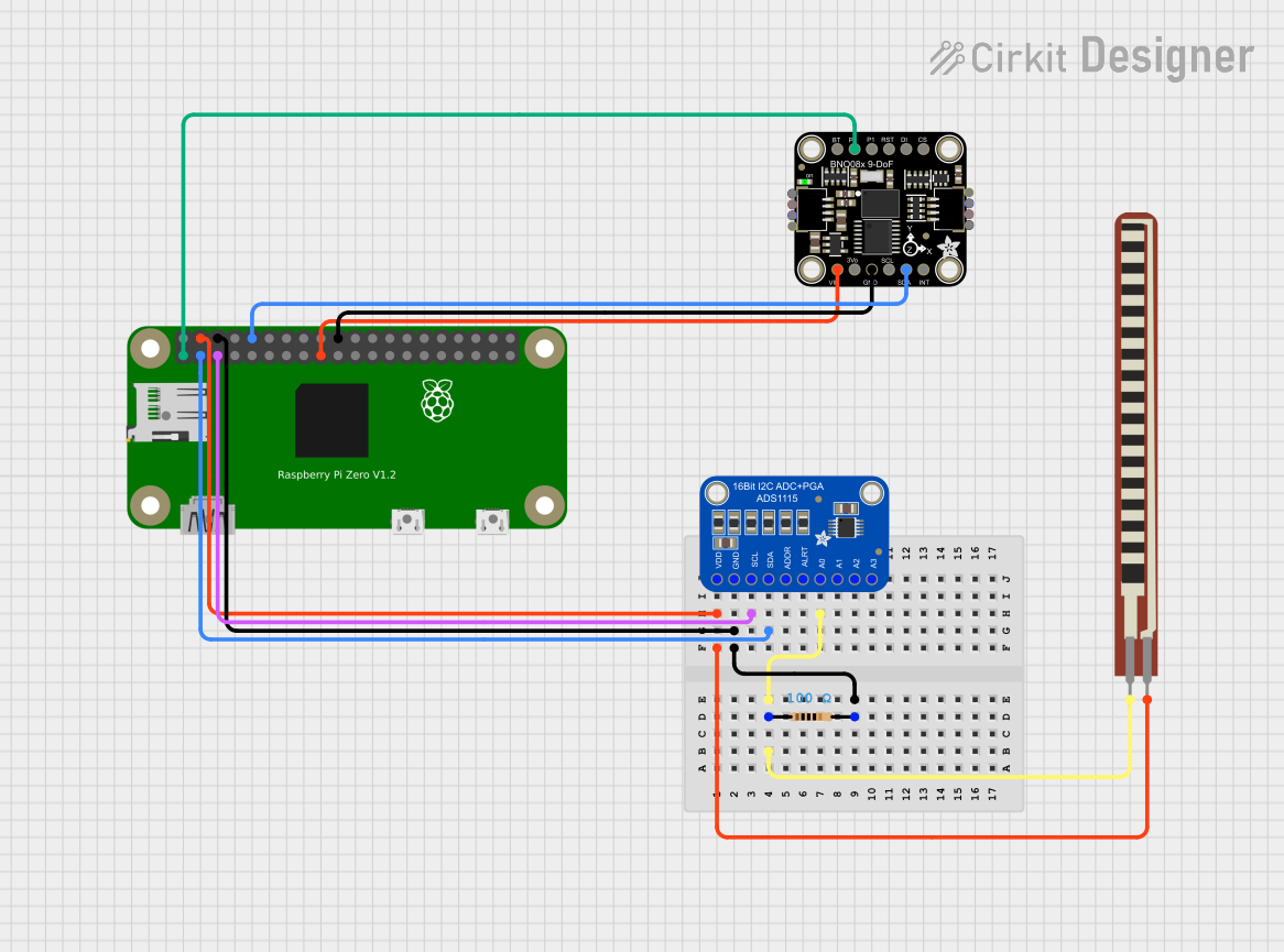
Usage Instructions
How to Use the Component in a Circuit
- Power the Module: Connect the VIN pin to a 3.3V or 5V power source and the GND pin to ground.
- Choose Communication Protocol:
- For I²C: Connect the SCL and SDA pins to the corresponding I²C pins on your microcontroller.
- For SPI: Connect the SCL, SDA, and CS pins to the SPI clock, MOSI, and chip select pins, respectively.
- Install Required Libraries: If using an Arduino, install the Adafruit LSM9DS1 library via the Arduino Library Manager.
- Write or Upload Code: Use the example code provided in the library or write custom code to read sensor data.
Important Considerations and Best Practices
- Bypass Capacitor: Place a 0.1µF decoupling capacitor near the VIN pin to reduce noise.
- I²C Pull-Up Resistors: Ensure that your I²C bus has appropriate pull-up resistors (typically 4.7kΩ).
- Sensor Calibration: Perform calibration for the accelerometer, gyroscope, and magnetometer to improve accuracy.
- Mounting Orientation: Secure the module firmly to avoid vibrations that could affect readings.
Example Code for Arduino UNO
Below is an example of how to read data from the Adafruit 9-DOF sensor using I²C:
#include <Wire.h>
#include <Adafruit_Sensor.h>
#include <Adafruit_LSM9DS1.h>

// Create an instance of the LSM9DS1 sensor
Adafruit_LSM9DS1 lsm = Adafruit_LSM9DS1();

// Define I2C addresses for the accelerometer/gyro and magnetometer
#define LSM9DS1_XG_ADDRESS (0x6B)
#define LSM9DS1_M_ADDRESS  (0x1E)

void setup() {
  Serial.begin(115200);
  while (!Serial) {
    delay(10); // Wait for Serial to initialize
  }

  // Initialize the sensor
  if (!lsm.begin()) {
    Serial.println("Failed to initialize LSM9DS1 sensor!");
    while (1);
  }
  Serial.println("LSM9DS1 sensor initialized successfully!");

  // Set sensor ranges (optional)
  lsm.setupAccel(lsm.LSM9DS1_ACCELRANGE_2G); // Accelerometer range: ±2g
  lsm.setupGyro(lsm.LSM9DS1_GYROSCALE_245DPS); // Gyroscope range: ±245°/s
  lsm.setupMag(lsm.LSM9DS1_MAGGAIN_4GAUSS); // Magnetometer range: ±4 gauss
}

void loop() {
  // Read accelerometer data
  sensors_event_t accel, gyro, mag;
  lsm.getEvent(&accel, &gyro, &mag);

  // Print accelerometer data
  Serial.print("Accel X: "); Serial.print(accel.acceleration.x); Serial.print(" m/s^2 ");
  Serial.print("Y: "); Serial.print(accel.acceleration.y); Serial.print(" m/s^2 ");
  Serial.print("Z: "); Serial.print(accel.acceleration.z); Serial.println(" m/s^2");

  // Print gyroscope data
  Serial.print("Gyro X: "); Serial.print(gyro.gyro.x); Serial.print(" rad/s ");
  Serial.print("Y: "); Serial.print(gyro.gyro.y); Serial.print(" rad/s ");
  Serial.print("Z: "); Serial.print(gyro.gyro.z); Serial.println(" rad/s");

  // Print magnetometer data
  Serial.print("Mag X: "); Serial.print(mag.magnetic.x); Serial.print(" gauss ");
  Serial.print("Y: "); Serial.print(mag.magnetic.y); Serial.print(" gauss ");
  Serial.print("Z: "); Serial.print(mag.magnetic.z); Serial.println(" gauss");

  delay(500); // Delay for readability
}
Troubleshooting and FAQs
Common Issues and Solutions
Sensor Not Detected:
- Ensure the wiring is correct and matches the selected communication protocol.
- Verify that the I²C addresses (0x6B and 0x1E) are not conflicting with other devices on the bus.
- Check for loose connections or damaged wires.
Inaccurate Readings:
- Perform a full calibration of the accelerometer, gyroscope, and magnetometer.
- Minimize external magnetic interference for the magnetometer.
- Ensure the module is mounted securely to avoid vibrations.
Communication Errors:
- Confirm that the correct pull-up resistors are in place for I²C communication.
- If using SPI, verify the chip select (CS) pin is properly configured in the code.
FAQs
Q: Can I use this module with a 3.3V microcontroller?
- A: Yes, the module is compatible with both 3.3V and 5V logic levels.
Q: How do I switch between I²C and SPI modes?
- A: By default, the module operates in I²C mode. To use SPI, connect the CS pin to your microcontroller and configure the library accordingly.
Q: Do I need to calibrate the sensors every time I use them?
- A: Calibration is recommended during initial setup or if the module is moved to a new environment.
This documentation provides a comprehensive guide to using the Adafruit 9-DOF sensor module effectively.