Cirkit Designer Logo
Cirkit Designer
Your all-in-one circuit design IDE
Home / 
Component Documentation

How to Use 5V, 3A Step-Up/Step-Down Voltage Regulator S13V30F5: Examples, Pinouts, and Specs

Image of 5V, 3A Step-Up/Step-Down Voltage Regulator S13V30F5
Cirkit Designer LogoDesign with 5V, 3A Step-Up/Step-Down Voltage Regulator S13V30F5 in Cirkit Designer

Introduction

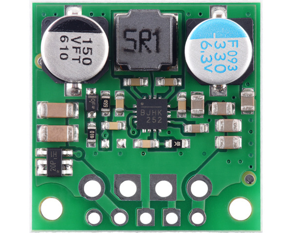
The 5V, 3A Step-Up/Step-Down Voltage Regulator S13V30F5 (Manufacturer Part ID: 4082) by Pololu is a versatile DC-DC converter designed to provide a stable 5V output regardless of whether the input voltage is higher or lower than 5V. This regulator is ideal for applications requiring a consistent 5V supply, such as powering microcontrollers, sensors, and other electronic devices.

Explore Projects Built with 5V, 3A Step-Up/Step-Down Voltage Regulator S13V30F5

Use Cirkit Designer to design, explore, and prototype these projects online. Some projects support real-time simulation. Click "Open Project" to start designing instantly!
Battery-Powered 18650 Li-ion Charger with USB Output and Adjustable Voltage Regulator
Image of Breadboard: A project utilizing 5V, 3A Step-Up/Step-Down Voltage Regulator S13V30F5 in a practical application
This circuit is a battery management and power supply system that uses three 3.7V batteries connected to a 3S 10A Li-ion 18650 Charger Protection Board Module for balanced charging and protection. The system includes a TP4056 Battery Charging Protection Module for additional charging safety, a Step Up Boost Power Converter to regulate and boost the voltage, and a USB regulator to provide a stable 5V output, controlled by a push switch.
Cirkit Designer LogoOpen Project in Cirkit Designer
AC to DC Power Supply with Voltage Regulation and LED Indicator
Image of Copy of 8 volt AC to DC convertor (1): A project utilizing 5V, 3A Step-Up/Step-Down Voltage Regulator S13V30F5 in a practical application
This circuit is a basic AC to DC power supply with voltage regulation. It includes a transformer to step down the AC voltage, a bridge rectifier made of 1N4007 diodes to convert AC to DC, an electrolytic capacitor for smoothing, and a voltage regulator to provide a stable DC output. An LED with a current-limiting resistor indicates the presence of the output voltage.
Cirkit Designer LogoOpen Project in Cirkit Designer
12V to 5V Power Supply with LED Indicator and Push Switch
Image of Power Supply LVCO: A project utilizing 5V, 3A Step-Up/Step-Down Voltage Regulator S13V30F5 in a practical application
This circuit is a 12V to 5V regulated power supply with an LED indicator. It uses a 5408 diode for reverse polarity protection, an LM340T5 7805 voltage regulator to step down the voltage to 5V, and a push switch to control the LED indicator. The circuit also includes capacitors for filtering and a resistor to limit the current through the LED.
Cirkit Designer LogoOpen Project in Cirkit Designer
AC to DC Power Supply with Voltage Regulation and Overcurrent Protection
Image of PENGATUR VOLTAN: A project utilizing 5V, 3A Step-Up/Step-Down Voltage Regulator S13V30F5 in a practical application
This circuit appears to be a power supply unit with a transformer for stepping down voltage, a bridge rectifier for converting AC to DC, and a voltage regulator for stabilizing the output voltage. It includes a Zener diode for overvoltage protection, capacitors for smoothing out ripples in the DC supply, and a fuse for overcurrent protection. A toggle switch and a rocker switch are used to control the power flow, and there is an LED indicator connected through resistors, likely for power-on indication.
Cirkit Designer LogoOpen Project in Cirkit Designer

Explore Projects Built with 5V, 3A Step-Up/Step-Down Voltage Regulator S13V30F5

Use Cirkit Designer to design, explore, and prototype these projects online. Some projects support real-time simulation. Click "Open Project" to start designing instantly!
Image of Breadboard: A project utilizing 5V, 3A Step-Up/Step-Down Voltage Regulator S13V30F5 in a practical application
Battery-Powered 18650 Li-ion Charger with USB Output and Adjustable Voltage Regulator
This circuit is a battery management and power supply system that uses three 3.7V batteries connected to a 3S 10A Li-ion 18650 Charger Protection Board Module for balanced charging and protection. The system includes a TP4056 Battery Charging Protection Module for additional charging safety, a Step Up Boost Power Converter to regulate and boost the voltage, and a USB regulator to provide a stable 5V output, controlled by a push switch.
Cirkit Designer LogoOpen Project in Cirkit Designer
Image of Copy of 8 volt AC to DC convertor (1): A project utilizing 5V, 3A Step-Up/Step-Down Voltage Regulator S13V30F5 in a practical application
AC to DC Power Supply with Voltage Regulation and LED Indicator
This circuit is a basic AC to DC power supply with voltage regulation. It includes a transformer to step down the AC voltage, a bridge rectifier made of 1N4007 diodes to convert AC to DC, an electrolytic capacitor for smoothing, and a voltage regulator to provide a stable DC output. An LED with a current-limiting resistor indicates the presence of the output voltage.
Cirkit Designer LogoOpen Project in Cirkit Designer
Image of Power Supply LVCO: A project utilizing 5V, 3A Step-Up/Step-Down Voltage Regulator S13V30F5 in a practical application
12V to 5V Power Supply with LED Indicator and Push Switch
This circuit is a 12V to 5V regulated power supply with an LED indicator. It uses a 5408 diode for reverse polarity protection, an LM340T5 7805 voltage regulator to step down the voltage to 5V, and a push switch to control the LED indicator. The circuit also includes capacitors for filtering and a resistor to limit the current through the LED.
Cirkit Designer LogoOpen Project in Cirkit Designer
Image of PENGATUR VOLTAN: A project utilizing 5V, 3A Step-Up/Step-Down Voltage Regulator S13V30F5 in a practical application
AC to DC Power Supply with Voltage Regulation and Overcurrent Protection
This circuit appears to be a power supply unit with a transformer for stepping down voltage, a bridge rectifier for converting AC to DC, and a voltage regulator for stabilizing the output voltage. It includes a Zener diode for overvoltage protection, capacitors for smoothing out ripples in the DC supply, and a fuse for overcurrent protection. A toggle switch and a rocker switch are used to control the power flow, and there is an LED indicator connected through resistors, likely for power-on indication.
Cirkit Designer LogoOpen Project in Cirkit Designer

Common Applications and Use Cases

  • Powering microcontrollers like Arduino, Raspberry Pi, or ESP32.
  • Supplying stable voltage to sensors and actuators in robotics.
  • Battery-powered devices where input voltage fluctuates (e.g., Li-ion or AA batteries).
  • Portable electronics requiring a reliable 5V output.
  • Prototyping and development boards.

Technical Specifications

The following table outlines the key technical details of the S13V30F5 voltage regulator:

Parameter Value
Output Voltage 5V ± 4%
Maximum Output Current 3A
Input Voltage Range 2.8V to 22V
Efficiency Up to 95%
Quiescent Current ~0.4 mA (no load, 5V input)
Switching Frequency ~1.5 MHz
Operating Temperature -40°C to +85°C
Dimensions 0.9" × 0.6" × 0.1" (23 × 15 × 3 mm)
Weight 1.2 g

Pin Configuration and Descriptions

The S13V30F5 regulator has three main pins for easy integration into circuits. The table below describes each pin:

Pin Name Description
VIN Input voltage pin. Connect to a DC power source (2.8V to 22V).
GND Ground pin. Connect to the ground of the circuit.
VOUT Output voltage pin. Provides a regulated 5V output with a maximum current of 3A.

Usage Instructions

How to Use the Component in a Circuit

  1. Connect the Input Voltage (VIN):

    • Attach the VIN pin to a DC power source within the range of 2.8V to 22V.
    • Ensure the power source can supply sufficient current for your load.
  2. Connect the Ground (GND):

    • Connect the GND pin to the ground of your circuit.
  3. Connect the Output Voltage (VOUT):

    • Attach the VOUT pin to the device or circuit requiring a 5V supply.
    • Ensure the total current draw does not exceed 3A.
  4. Add Capacitors (Optional but Recommended):

    • For improved stability, place a capacitor (e.g., 10 µF) close to the VIN and GND pins.
    • Similarly, add a capacitor (e.g., 10 µF) between VOUT and GND.

Important Considerations and Best Practices

  • Heat Dissipation: At high currents, the regulator may generate heat. Ensure adequate ventilation or consider adding a heatsink if necessary.
  • Input Voltage Range: Do not exceed the maximum input voltage of 22V, as this may damage the regulator.
  • Load Current: Ensure the connected load does not draw more than 3A to avoid overloading the regulator.
  • Polarity Protection: The regulator does not have built-in reverse polarity protection. Double-check connections before powering the circuit.

Example: Using with an Arduino UNO

The S13V30F5 can be used to power an Arduino UNO from a battery pack. Below is an example circuit and Arduino code:

Circuit Connections

  • Connect the VIN pin of the regulator to the positive terminal of a 4xAA battery pack (6V).
  • Connect the GND pin of the regulator to the negative terminal of the battery pack.
  • Connect the VOUT pin of the regulator to the 5V pin of the Arduino UNO.
  • Connect the GND pin of the regulator to the GND pin of the Arduino UNO.

Arduino Code Example

// Example code to blink an LED connected to pin 13 of the Arduino UNO
// Ensure the Arduino is powered via the S13V30F5 regulator.

void setup() {
  pinMode(13, OUTPUT); // Set pin 13 as an output
}

void loop() {
  digitalWrite(13, HIGH); // Turn the LED on
  delay(1000);            // Wait for 1 second
  digitalWrite(13, LOW);  // Turn the LED off
  delay(1000);            // Wait for 1 second
}

Troubleshooting and FAQs

Common Issues and Solutions

  1. No Output Voltage:

    • Cause: Incorrect wiring or insufficient input voltage.
    • Solution: Verify all connections and ensure the input voltage is within the 2.8V to 22V range.
  2. Overheating:

    • Cause: Excessive load current or poor ventilation.
    • Solution: Reduce the load current or improve airflow around the regulator.
  3. Output Voltage Fluctuations:

    • Cause: Insufficient input power or lack of decoupling capacitors.
    • Solution: Use a stable power source and add capacitors near the VIN and VOUT pins.
  4. Regulator Not Working with Low Input Voltage:

    • Cause: Input voltage is below the minimum required for the load.
    • Solution: Ensure the input voltage is at least 2.8V and can supply sufficient current.

FAQs

Q: Can I use this regulator to power a Raspberry Pi?
A: Yes, but ensure the total current draw (including peripherals) does not exceed 3A.

Q: Does the regulator have reverse polarity protection?
A: No, the regulator does not have built-in reverse polarity protection. Double-check connections before powering the circuit.

Q: Can I use this regulator with a solar panel?
A: Yes, as long as the solar panel's output voltage is within the 2.8V to 22V range and can supply sufficient current.

Q: What is the efficiency of the regulator?
A: The efficiency can reach up to 95%, depending on the input voltage and load conditions.