How to Use DAPLINK ARM Debugger/Downloader: Examples, Pinouts, and Specs
Introduction
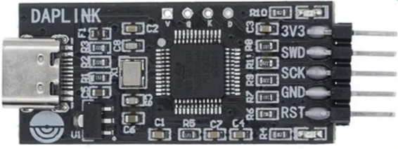
The DAPLINK ARM Debugger/Downloader is a versatile tool designed for debugging and programming ARM microcontrollers. It provides developers with a seamless interface to download firmware and debug applications via a USB connection. This tool is widely used in embedded systems development due to its ease of use, compatibility with multiple IDEs, and support for a variety of ARM Cortex-M microcontrollers.
Explore Projects Built with DAPLINK ARM Debugger/Downloader

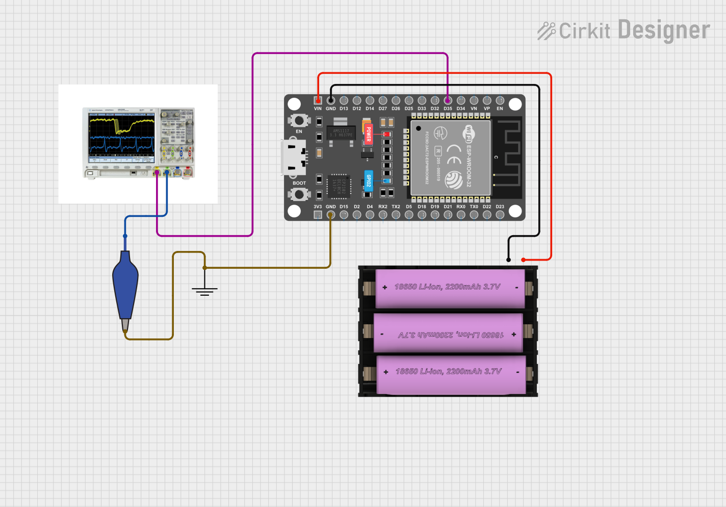
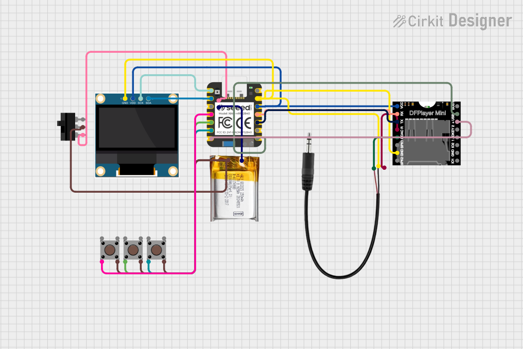

Explore Projects Built with DAPLINK ARM Debugger/Downloader
Common Applications and Use Cases
- Firmware programming for ARM Cortex-M microcontrollers
- Debugging embedded applications in real-time
- Educational purposes for learning ARM-based development
- Prototyping and testing embedded systems
- Integration with IDEs such as Keil, IAR Embedded Workbench, and ARM Mbed
Technical Specifications
Key Technical Details
- Supported Microcontrollers: ARM Cortex-M series
- Interface: USB 2.0 (Type-A or Type-C, depending on the model)
- Power Supply: 5V via USB
- Supported Protocols: SWD (Serial Wire Debug), CMSIS-DAP
- Operating Systems: Windows, macOS, Linux
- Firmware Update: Supported via drag-and-drop file transfer
- LED Indicators: Status and activity indicators for debugging and programming
Pin Configuration and Descriptions
The DAPLINK debugger typically connects to the target microcontroller via a 10-pin or 20-pin SWD header. Below is the pinout for the standard 10-pin SWD connector:
| Pin | Name | Description |
|---|---|---|
| 1 | VCC (Target) | Target microcontroller power supply (3.3V) |
| 2 | SWDIO | Serial Wire Debug I/O |
| 3 | GND | Ground |
| 4 | SWCLK | Serial Wire Debug Clock |
| 5 | GND | Ground |
| 6 | SWO (Optional) | Serial Wire Output (for trace debugging) |
| 7 | NC | Not Connected |
| 8 | NC | Not Connected |
| 9 | GND | Ground |
| 10 | RESET | Target microcontroller reset |
Usage Instructions
How to Use the DAPLINK ARM Debugger/Downloader
Connect the Debugger to the Target Microcontroller:
- Use the appropriate SWD cable to connect the DAPLINK debugger to the target microcontroller's SWD header.
- Ensure the pin alignment matches the pinout described above.
Connect the Debugger to Your Computer:
- Plug the debugger into your computer's USB port using the provided USB cable.
- The debugger should appear as a USB mass storage device on your computer.
Install Required Drivers and Software:
- Install the CMSIS-DAP drivers if required (usually pre-installed on most IDEs).
- Use an IDE such as Keil, IAR, or Mbed Studio to configure the debugger.
Program the Microcontroller:
- Drag and drop the compiled firmware file (e.g.,
.binor.hex) onto the debugger's USB drive. - The debugger will automatically program the target microcontroller.
- Drag and drop the compiled firmware file (e.g.,
Debug the Application:
- Open your IDE and configure the debugger settings (e.g., select CMSIS-DAP as the debugger).
- Set breakpoints, watch variables, and step through the code as needed.
Important Considerations and Best Practices
- Ensure the target microcontroller is powered correctly before connecting the debugger.
- Avoid connecting or disconnecting the debugger while the system is powered on to prevent damage.
- Keep the firmware of the DAPLINK debugger updated to ensure compatibility with the latest tools.
- Use short and high-quality SWD cables to minimize signal degradation.
Example: Using DAPLINK with Arduino IDE
While DAPLINK is not directly compatible with Arduino boards, it can be used with ARM-based boards like the Arduino Nano 33 BLE. Below is an example of configuring the debugger with an ARM-based board:
// Example code for blinking an LED on an ARM-based board
// Ensure the debugger is connected and the board is powered

#include "mbed.h" // Include the mbed library for ARM-based development

DigitalOut led(LED1); // Define the onboard LED pin

int main() {
    while (true) {
        led = !led; // Toggle the LED state
        ThisThread::sleep_for(500ms); // Wait for 500 milliseconds
    }
}
Troubleshooting and FAQs
Common Issues and Solutions
Debugger Not Recognized by the Computer:
- Ensure the USB cable is functional and properly connected.
- Try a different USB port or restart your computer.
- Update the debugger's firmware if it is outdated.
Target Microcontroller Not Detected:
- Verify the SWD cable connections and pin alignment.
- Check if the target microcontroller is powered correctly.
- Ensure the correct target device is selected in the IDE.
Firmware Programming Fails:
- Confirm that the firmware file is in the correct format (
.binor.hex). - Ensure there is no write protection enabled on the target microcontroller.
- Confirm that the firmware file is in the correct format (
Debugging Does Not Start:
- Verify that the debugger is configured correctly in the IDE.
- Check for any conflicting software or drivers on your computer.
FAQs
Q: Can I use DAPLINK with non-ARM microcontrollers?
A: No, DAPLINK is specifically designed for ARM Cortex-M microcontrollers and does not support other architectures.
Q: How do I update the DAPLINK firmware?
A: Drag and drop the firmware update file onto the debugger's USB drive. The debugger will automatically update itself.
Q: What IDEs are compatible with DAPLINK?
A: DAPLINK is compatible with Keil, IAR Embedded Workbench, ARM Mbed Studio, and other IDEs that support CMSIS-DAP.
Q: Can I use DAPLINK for trace debugging?
A: Yes, if your target microcontroller supports SWO (Serial Wire Output), you can use it for trace debugging.
By following this documentation, you can effectively use the DAPLINK ARM Debugger/Downloader for your embedded development projects.