How to Use 7_Segment_LED-FIAX: Examples, Pinouts, and Specs
Introduction
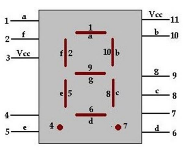
The 7_Segment_LED-FIAX is a versatile 7-segment LED display designed to display decimal numerals and some alphabetic characters. It consists of seven individual segments (labeled A through G) that can be lit in various combinations to represent numbers (0-9) and certain letters. This component is widely used in digital clocks, electronic meters, and other devices requiring a simple, human-readable numeric display.
Explore Projects Built with 7_Segment_LED-FIAX


Explore Projects Built with 7_Segment_LED-FIAX
Technical Specifications
Key Technical Details
| Parameter | Value |
|---|---|
| Manufacturer | FIAX |
| Part ID | 7_Segment_LED-FIAX |
| Operating Voltage | 2V per segment |
| Forward Current | 20mA per segment |
| Power Dissipation | 100mW |
| Display Type | Common Anode / Common Cathode |
| Segment Color | Red |
| Number of Pins | 10 |
Pin Configuration and Descriptions
Common Anode Configuration
| Pin Number | Segment Connection |
|---|---|
| 1 | E |
| 2 | D |
| 3 | Common Anode |
| 4 | C |
| 5 | Decimal Point (DP) |
| 6 | B |
| 7 | A |
| 8 | Common Anode |
| 9 | F |
| 10 | G |
Common Cathode Configuration
| Pin Number | Segment Connection |
|---|---|
| 1 | E |
| 2 | D |
| 3 | Common Cathode |
| 4 | C |
| 5 | Decimal Point (DP) |
| 6 | B |
| 7 | A |
| 8 | Common Cathode |
| 9 | F |
| 10 | G |
Usage Instructions
How to Use the Component in a Circuit
- Identify the Configuration: Determine whether your 7_Segment_LED-FIAX is a common anode or common cathode type.
- Connect the Common Pin:
- For common anode, connect the common pins (3 and 8) to the positive supply voltage.
- For common cathode, connect the common pins (3 and 8) to ground.
- Connect the Segment Pins: Connect each segment pin (A-G) to the corresponding control signal from your microcontroller or driver circuit. Use current-limiting resistors (typically 220Ω to 1kΩ) to prevent excessive current through the LEDs.
- Control the Segments: Apply the appropriate voltage to each segment pin to light up the desired segments. For common anode, pull the segment pins low to light them up. For common cathode, pull the segment pins high.
Important Considerations and Best Practices
- Current Limiting: Always use current-limiting resistors to protect the LEDs from excessive current.
- Power Supply: Ensure your power supply can handle the total current draw of all segments that may be lit simultaneously.
- Heat Dissipation: Be mindful of power dissipation and heat generation, especially if multiple segments are lit for extended periods.
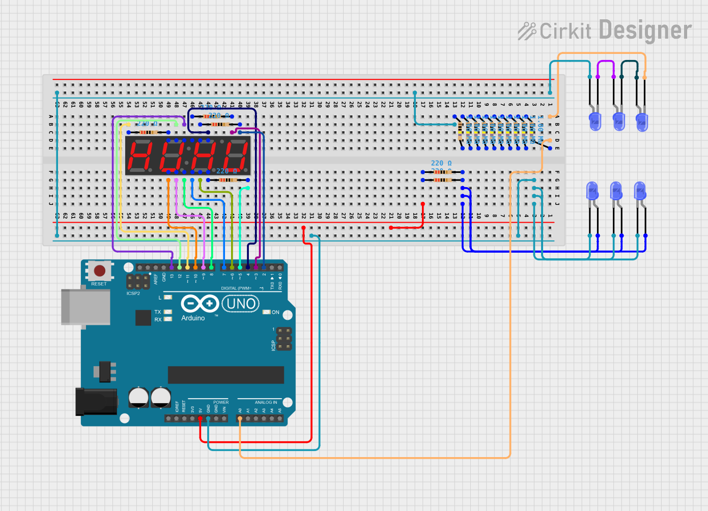
Example: Connecting to an Arduino UNO
Circuit Diagram

Arduino Code
// Pin configuration for 7_Segment_LED-FIAX
const int segmentPins[] = {2, 3, 4, 5, 6, 7, 8}; // A, B, C, D, E, F, G
const int commonPin = 9; // Common anode or cathode

// Segment patterns for digits 0-9
const byte digitPatterns[] = {
  B00111111, // 0
  B00000110, // 1
  B01011011, // 2
  B01001111, // 3
  B01100110, // 4
  B01101101, // 5
  B01111101, // 6
  B00000111, // 7
  B01111111, // 8
  B01101111  // 9
};

void setup() {
  // Set segment pins as outputs
  for (int i = 0; i < 7; i++) {
    pinMode(segmentPins[i], OUTPUT);
  }
  pinMode(commonPin, OUTPUT);
  digitalWrite(commonPin, LOW); // For common anode, set to HIGH
}

void loop() {
  for (int digit = 0; digit < 10; digit++) {
    displayDigit(digit);
    delay(1000); // Display each digit for 1 second
  }
}

void displayDigit(int digit) {
  byte pattern = digitPatterns[digit];
  for (int i = 0; i < 7; i++) {
    digitalWrite(segmentPins[i], bitRead(pattern, i));
  }
}
Troubleshooting and FAQs
Common Issues
Segments Not Lighting Up:
- Check Connections: Ensure all connections are secure and correct.
- Verify Resistors: Make sure current-limiting resistors are in place and of the correct value.
- Power Supply: Confirm that the power supply is providing the correct voltage and current.
Incorrect Digits Displayed:
- Check Code: Verify that the segment patterns in your code match the desired digits.
- Pin Mapping: Ensure the segment pins are correctly mapped in your code.
Flickering Display:
- Power Stability: Ensure your power supply is stable and not fluctuating.
- Loose Connections: Check for any loose or intermittent connections.
FAQs
Q: Can I use the 7_Segment_LED-FIAX with a 3.3V microcontroller? A: Yes, but ensure the forward voltage of each segment is compatible and adjust the current-limiting resistors accordingly.
Q: How do I display letters on the 7_Segment_LED-FIAX? A: You can create custom segment patterns for letters, similar to how digits are displayed. Note that not all letters can be accurately represented.
Q: Can I multiplex multiple 7-segment displays? A: Yes, you can use multiplexing techniques to control multiple displays with fewer I/O pins. This typically involves rapidly switching between displays.
This documentation provides a comprehensive guide to using the 7_Segment_LED-FIAX, ensuring both beginners and experienced users can effectively integrate this component into their projects.