
How to Use Arduino Ethernet (pre-Rev3): Examples, Pinouts, and Specs
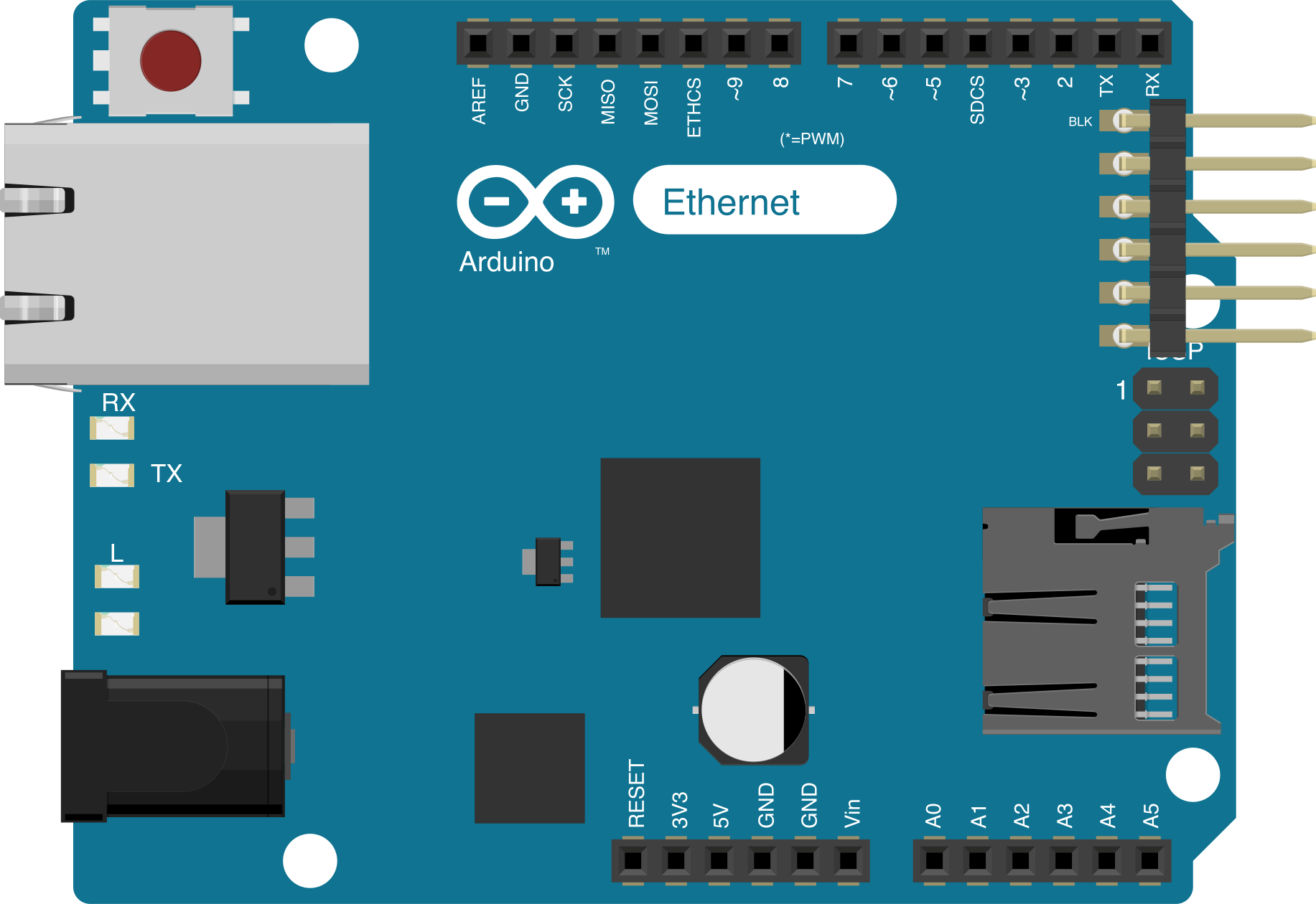
 Design with Arduino Ethernet (pre-Rev3) in Cirkit Designer
Introduction
The Arduino Ethernet (pre-Rev3) is a microcontroller board developed by Arduino, based on the ATmega328 microcontroller. It features an integrated Ethernet controller (WIZnet W5100) that enables network connectivity, making it ideal for Internet of Things (IoT) applications, web-based projects, and remote monitoring systems. This board combines the simplicity of Arduino programming with the power of Ethernet communication, allowing users to create connected devices with ease.
Explore Projects Built with Arduino Ethernet (pre-Rev3)
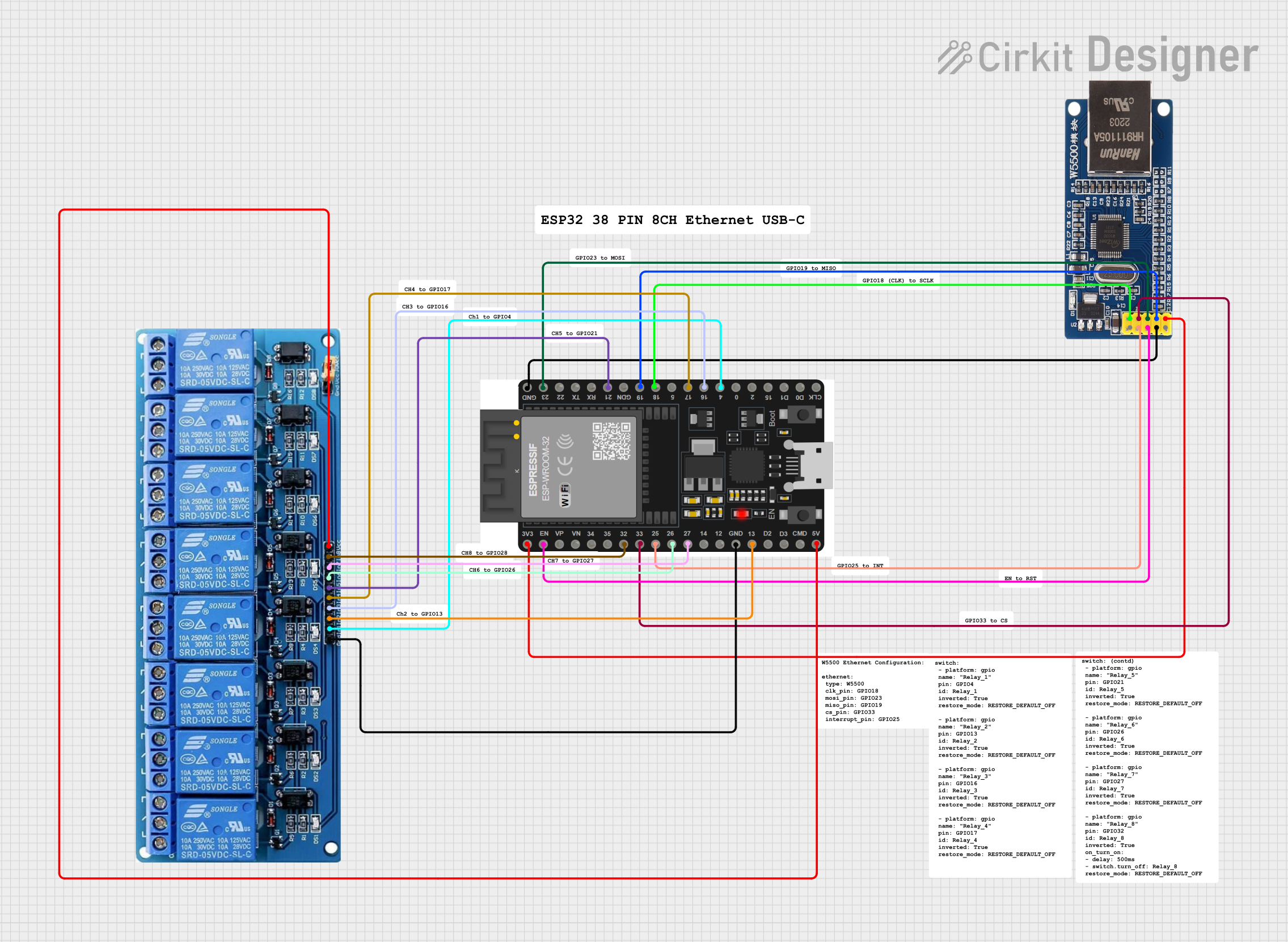 Open Project in Cirkit Designer
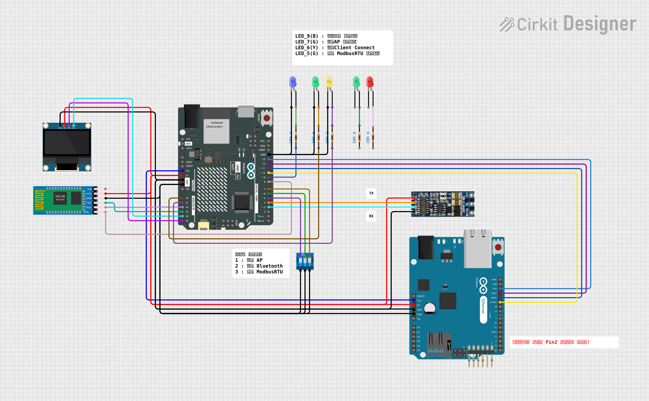 Open Project in Cirkit Designer
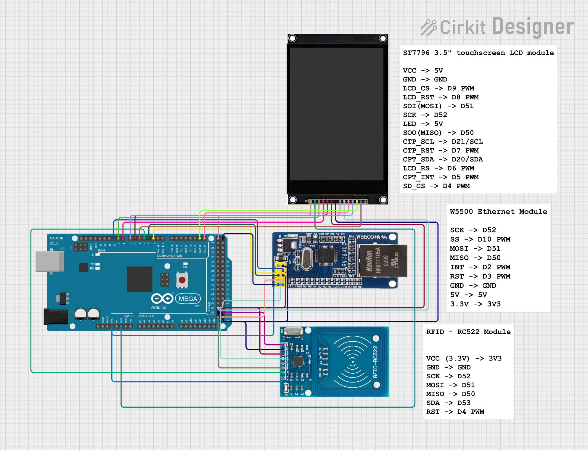 Open Project in Cirkit Designer
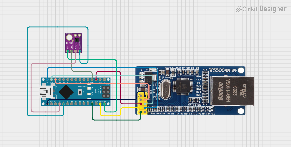 Open Project in Cirkit Designer
Explore Projects Built with Arduino Ethernet (pre-Rev3)
Open Project in Cirkit DesignerOpen Project in Cirkit DesignerOpen Project in Cirkit DesignerOpen Project in Cirkit DesignerCommon Applications and Use Cases
- IoT devices and smart home systems
- Web servers for remote control and monitoring
- Data logging and transmission over a network
- Network-enabled sensors and actuators
- Educational projects involving networking and communication
Technical Specifications
Below are the key technical details of the Arduino Ethernet (pre-Rev3):
General Specifications
| Parameter | Value |
|---|---|
| Microcontroller | ATmega328 |
| Operating Voltage | 5V |
| Input Voltage (recommended) | 7-12V |
| Input Voltage (limits) | 6-20V |
| Digital I/O Pins | 14 (6 PWM outputs) |
| Analog Input Pins | 6 |
| DC Current per I/O Pin | 40 mA |
| Flash Memory | 32 KB (2 KB used by bootloader) |
| SRAM | 2 KB |
| EEPROM | 1 KB |
| Clock Speed | 16 MHz |
| Ethernet Controller | WIZnet W5100 |
| Ethernet Speed | 10/100 Mbps |
| Dimensions | 73.2 mm x 53.3 mm |
Pin Configuration and Descriptions
The Arduino Ethernet (pre-Rev3) has a standard pinout similar to other Arduino boards, with additional pins for Ethernet functionality.
Digital Pins
| Pin Number | Functionality |
|---|---|
| 0 (RX) | Serial Receive (UART) |
| 1 (TX) | Serial Transmit (UART) |
| 2-13 | General-purpose digital I/O |
| 3, 5, 6, 9, 10, 11 | PWM outputs |
Analog Pins
| Pin Number | Functionality |
|---|---|
| A0-A5 | Analog inputs (10-bit resolution) |
Ethernet-Specific Pins
| Pin Number | Functionality |
|---|---|
| 10 | Ethernet chip select (CS) |
| 11 | SPI MOSI (Master Out Slave In) |
| 12 | SPI MISO (Master In Slave Out) |
| 13 | SPI SCK (Serial Clock) |
Power Pins
| Pin Name | Functionality |
|---|---|
| VIN | Input voltage to the board (7-12V) |
| 5V | Regulated 5V output |
| 3.3V | Regulated 3.3V output |
| GND | Ground |
| IOREF | Reference voltage for I/O pins |
Usage Instructions
How to Use the Arduino Ethernet (pre-Rev3) in a Circuit
- Power the Board: Connect an external power supply (7-12V) to the VIN pin or use the DC barrel jack.
- Connect to Ethernet: Plug an Ethernet cable into the RJ45 port on the board.
- Program the Board: Use the Arduino IDE to write and upload your sketch via the USB interface.
- Use the Ethernet Library: Include the
Ethernet.hlibrary in your sketch to enable Ethernet functionality. - Connect Peripherals: Attach sensors, actuators, or other devices to the digital and analog pins as needed.
Important Considerations and Best Practices
- Power Supply: Ensure the input voltage is within the recommended range (7-12V) to avoid damaging the board.
- Ethernet Shield Compatibility: The Ethernet controller (WIZnet W5100) uses the SPI interface, so avoid conflicts with other SPI devices.
- Static IP vs. DHCP: Decide whether to use a static IP address or DHCP for network configuration. DHCP is easier for beginners, but static IPs are useful for fixed network setups.
- Shielding: Use a shielded Ethernet cable to minimize interference in noisy environments.
Example Code for Arduino Ethernet
Below is an example sketch to set up a simple web server using the Arduino Ethernet (pre-Rev3):
#include <SPI.h>
#include <Ethernet.h>

// MAC address and IP address for the Ethernet shield
byte mac[] = { 0xDE, 0xAD, 0xBE, 0xEF, 0xFE, 0xED };
IPAddress ip(192, 168, 1, 177); // Static IP address
EthernetServer server(80); // Create a server on port 80

void setup() {
  // Start the Ethernet connection
  Ethernet.begin(mac, ip);
  // Start the server
  server.begin();
  Serial.begin(9600);
  Serial.println("Server is ready at http://192.168.1.177/");
}

void loop() {
  // Listen for incoming clients
  EthernetClient client = server.available();
  if (client) {
    Serial.println("New client connected");
    boolean currentLineIsBlank = true;
    while (client.connected()) {
      if (client.available()) {
        char c = client.read();
        Serial.write(c); // Print received data to Serial Monitor

        // Respond to the client with a simple HTML page
        if (c == '\n' && currentLineIsBlank) {
          client.println("HTTP/1.1 200 OK");
          client.println("Content-Type: text/html");
          client.println("Connection: close");
          client.println();
          client.println("<!DOCTYPE HTML>");
          client.println("<html>");
          client.println("<h1>Welcome to Arduino Ethernet!</h1>");
          client.println("</html>");
          break;
        }
        if (c == '\n') {
          currentLineIsBlank = true;
        } else if (c != '\r') {
          currentLineIsBlank = false;
        }
      }
    }
    // Give the client time to receive the data
    delay(1);
    client.stop();
    Serial.println("Client disconnected");
  }
}
Troubleshooting and FAQs
Common Issues and Solutions
Ethernet Not Connecting
- Cause: Incorrect MAC or IP address configuration.
- Solution: Double-check the MAC and IP address in your sketch. Ensure the IP address is within your network's range.
Board Not Responding
- Cause: Insufficient power supply.
- Solution: Use a power supply within the recommended range (7-12V).
SPI Conflicts
- Cause: Multiple SPI devices using the same pins.
- Solution: Ensure only one device is active on the SPI bus at a time. Use separate chip select (CS) pins for each device.
Slow Network Performance
- Cause: High network traffic or poor cable quality.
- Solution: Use a shielded Ethernet cable and minimize network congestion.
FAQs
Q: Can I use the Arduino Ethernet (pre-Rev3) with PoE (Power over Ethernet)?
A: No, the pre-Rev3 version does not support PoE. You will need an external power supply.
Q: Is the Arduino Ethernet compatible with the Arduino Uno shields?
A: Yes, the Arduino Ethernet has the same form factor as the Arduino Uno and is compatible with most Uno shields.
Q: How do I reset the Ethernet connection?
A: Call Ethernet.begin(mac, ip) again in your sketch to reinitialize the Ethernet connection.
Q: Can I use DHCP instead of a static IP?
A: Yes, replace Ethernet.begin(mac, ip) with Ethernet.begin(mac) to use DHCP.