
How to Use VL53L1X: Examples, Pinouts, and Specs
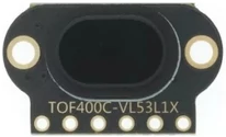
 Design with VL53L1X in Cirkit Designer
Introduction
The VL53L1X is a state-of-the-art time-of-flight (ToF) distance sensor manufactured by STMicroelectronics. It uses laser technology to measure distances with high accuracy, up to 4 meters. This sensor is compact, energy-efficient, and capable of operating in diverse lighting conditions, making it ideal for a wide range of applications.
Explore Projects Built with VL53L1X
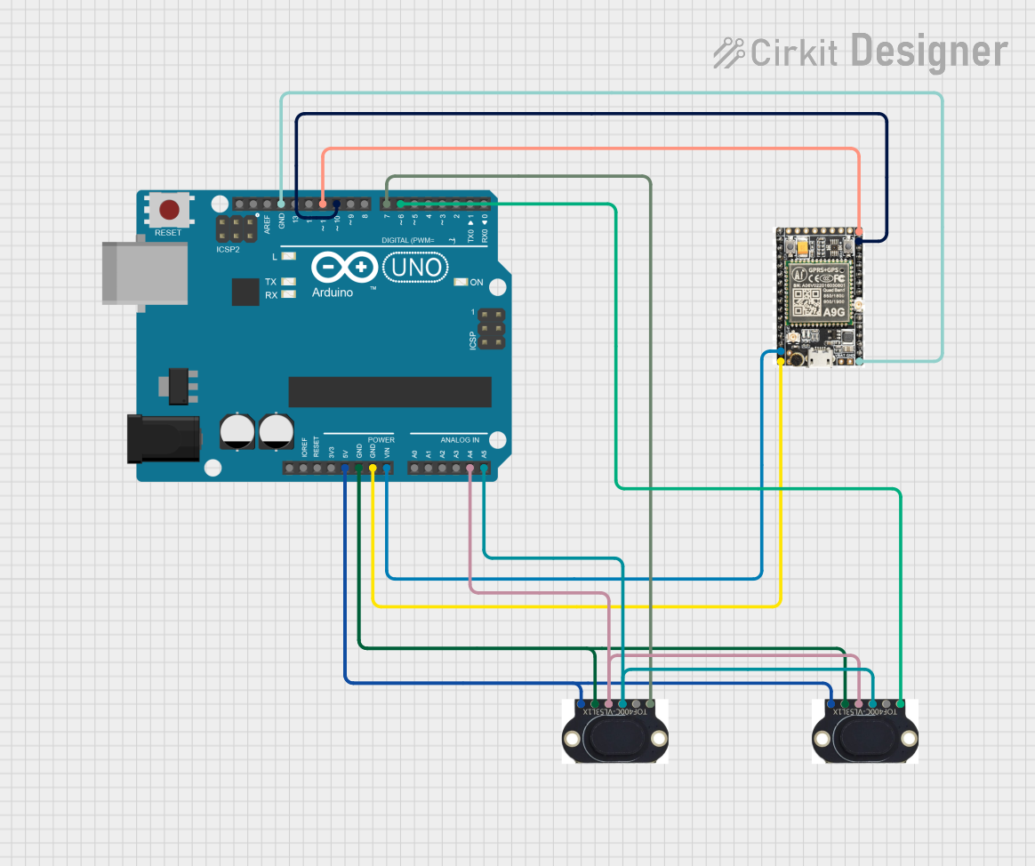 Open Project in Cirkit Designer
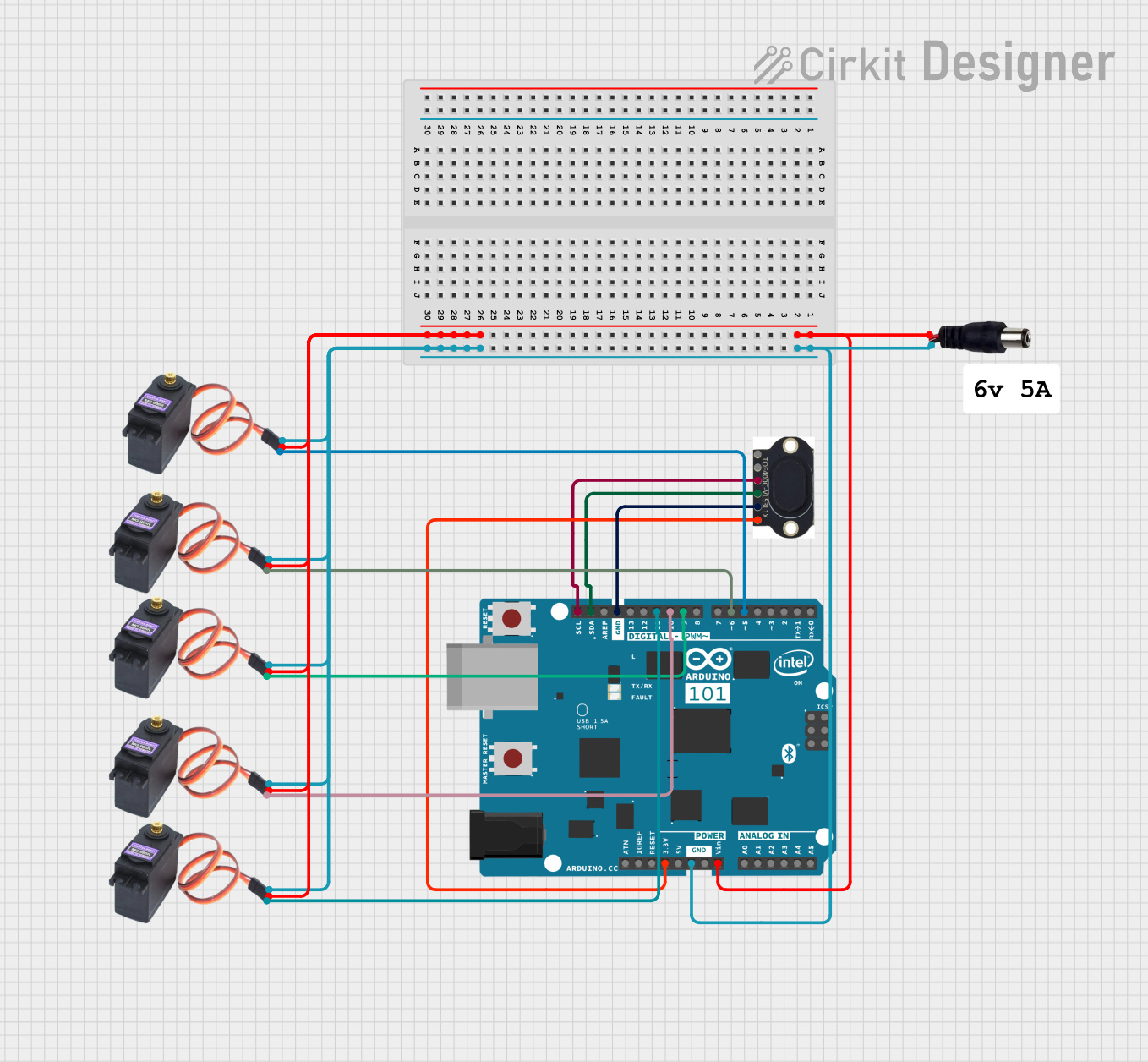 Open Project in Cirkit Designer
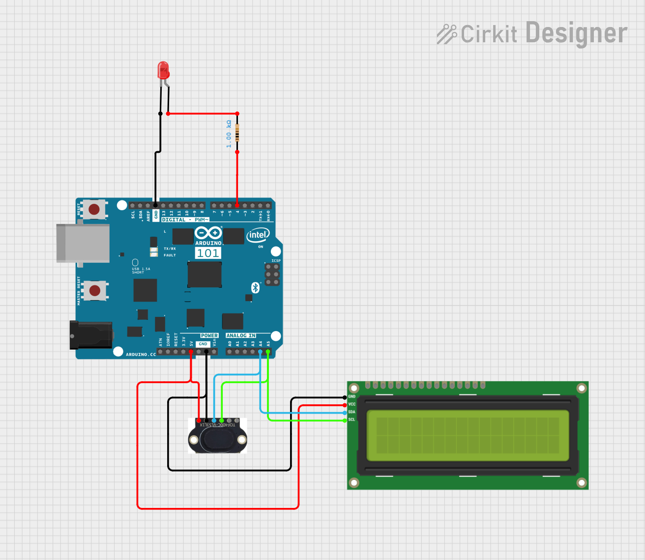 Open Project in Cirkit Designer
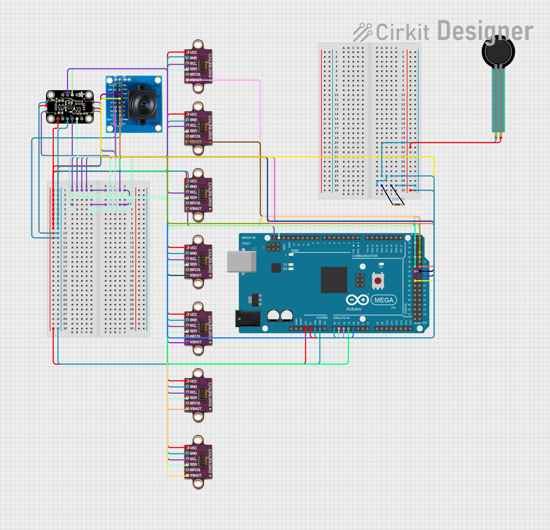 Open Project in Cirkit Designer
Explore Projects Built with VL53L1X
Open Project in Cirkit DesignerOpen Project in Cirkit DesignerOpen Project in Cirkit DesignerOpen Project in Cirkit DesignerCommon Applications and Use Cases
- Robotics for obstacle detection and navigation
- Drones for altitude measurement and collision avoidance
- Industrial automation for proximity sensing
- Smart home devices for gesture recognition
- Consumer electronics for presence detection
Technical Specifications
The VL53L1X is designed to deliver precise distance measurements with minimal power consumption. Below are its key technical details:
| Parameter | Value |
|---|---|
| Operating Voltage | 2.6V to 3.5V |
| Communication Interface | I²C |
| Measurement Range | 4 cm to 400 cm (0.04 m to 4 m) |
| Accuracy | ±1 mm |
| Field of View (FoV) | Programmable, up to 27° |
| Power Consumption | 20 mW (typical) |
| Operating Temperature Range | -20°C to +85°C |
| Dimensions | 4.9 mm x 2.5 mm x 1.56 mm |
Pin Configuration and Descriptions
The VL53L1X sensor module typically comes with the following pinout:
| Pin Name | Description |
|---|---|
| VIN | Power supply input (2.6V to 3.5V) |
| GND | Ground |
| SDA | I²C data line |
| SCL | I²C clock line |
| XSHUT | Shutdown pin (active low) |
| GPIO1 | Interrupt output (optional, configurable) |
Usage Instructions
The VL53L1X is straightforward to integrate into a circuit, thanks to its I²C interface. Below are the steps to use the sensor effectively:
Connecting the VL53L1X to an Arduino UNO
Wiring: Connect the VL53L1X to the Arduino UNO as follows:
VINto the Arduino's5Vpin (use a voltage regulator if needed).GNDto the Arduino'sGNDpin.SDAto the Arduino'sA4pin (I²C data line).SCLto the Arduino'sA5pin (I²C clock line).- Optionally, connect
XSHUTto a digital pin for shutdown control.
Install Libraries: Use the Arduino IDE to install the VL53L1X library. Navigate to Sketch > Include Library > Manage Libraries, search for "VL53L1X," and install the library by Pololu or Adafruit.
Upload Example Code: Use the following sample code to read distance measurements:
#include <Wire.h>
#include <VL53L1X.h>

VL53L1X sensor;

void setup() {
  Serial.begin(9600); // Initialize serial communication at 9600 baud
  Wire.begin();       // Initialize I²C communication

  sensor.setTimeout(500); // Set timeout for sensor operations
  if (!sensor.init()) {
    Serial.println("Failed to detect and initialize sensor!");
    while (1); // Halt execution if sensor initialization fails
  }

  sensor.setDistanceMode(VL53L1X::Long); // Set distance mode to 'Long'
  sensor.setMeasurementTimingBudget(50000); // Set timing budget (50ms)
  sensor.startContinuous(50); // Start continuous measurements every 50ms
}

void loop() {
  if (sensor.timeoutOccurred()) {
    Serial.println("Sensor timeout occurred!"); // Handle timeout errors
  }

  Serial.print("Distance: ");
  Serial.print(sensor.read());
  Serial.println(" mm"); // Print distance in millimeters
  delay(100); // Delay for readability
}
Important Considerations and Best Practices
- Power Supply: Ensure the sensor operates within its voltage range (2.6V to 3.5V). Use a voltage regulator if connecting to a 5V system.
- I²C Pull-Up Resistors: The I²C lines (
SDAandSCL) require pull-up resistors (typically 4.7 kΩ). Some breakout boards include these resistors. - Ambient Light: While the VL53L1X is designed to work in various lighting conditions, excessive ambient light may reduce accuracy.
- FoV Adjustment: The sensor's field of view can be programmed to suit specific applications. Refer to the datasheet for advanced configuration.
Troubleshooting and FAQs
Common Issues
Sensor Not Detected
- Cause: Incorrect wiring or I²C address mismatch.
- Solution: Verify connections and ensure the correct I²C address is used in the code.
Inaccurate Distance Measurements
- Cause: Reflective or transparent surfaces in the sensor's path.
- Solution: Use a matte surface or adjust the sensor's position.
Timeout Errors
- Cause: Sensor not responding within the set timeout period.
- Solution: Check power supply and ensure the sensor is not in shutdown mode.
Interference from Multiple Sensors
- Cause: Multiple VL53L1X sensors operating in close proximity.
- Solution: Use the
XSHUTpin to control and initialize sensors sequentially.
FAQs
Q1: Can the VL53L1X measure distances beyond 4 meters?
No, the maximum range of the VL53L1X is 4 meters. For longer ranges, consider other ToF sensors.
Q2: How can I reduce power consumption?
Use the XSHUT pin to put the sensor in shutdown mode when not in use.
Q3: Can the VL53L1X detect transparent objects?
The sensor may struggle with transparent or highly reflective objects. Use additional techniques, such as background subtraction, for better results.
Q4: Is the VL53L1X compatible with 5V logic?
The VL53L1X operates at 3.3V logic. Use a level shifter if connecting to a 5V system.
By following this documentation, users can effectively integrate and troubleshoot the VL53L1X sensor in their projects.