How to Use ESP32-WROOM-32D Development Board: Examples, Pinouts, and Specs
Introduction
The ESP32-WROOM-32D Development Board by VKTECH is a powerful and versatile microcontroller board designed for a wide range of applications. It features integrated Wi-Fi and Bluetooth capabilities, making it an excellent choice for IoT (Internet of Things) projects, prototyping, and embedded systems development. With its dual-core processor, ample GPIO pins, and support for various communication protocols, the ESP32-WROOM-32D is a go-to solution for developers and hobbyists alike.
Explore Projects Built with ESP32-WROOM-32D Development Board


Explore Projects Built with ESP32-WROOM-32D Development Board
Common Applications and Use Cases
- IoT devices and smart home automation
- Wireless sensor networks
- Wearable technology
- Robotics and automation systems
- Prototyping and educational projects
- Data logging and remote monitoring
Technical Specifications
The ESP32-WROOM-32D Development Board is built around the ESP32-WROOM-32D module, which is based on the ESP32-D0WDQ6 chip. Below are the key technical details:
Key Technical Details
| Parameter | Specification |
|---|---|
| Manufacturer | VKTECH |
| Part ID | ESP32-WROOM-32D |
| Microcontroller | ESP32-D0WDQ6 |
| Operating Voltage | 3.3V |
| Input Voltage (VIN) | 5V (via USB or external power supply) |
| Flash Memory | 4MB |
| SRAM | 520KB |
| Wi-Fi Standard | 802.11 b/g/n |
| Bluetooth Version | Bluetooth 4.2 (Classic + BLE) |
| GPIO Pins | 34 |
| ADC Channels | 18 |
| DAC Channels | 2 |
| Communication Interfaces | UART, SPI, I2C, I2S, CAN, PWM |
| Clock Speed | Up to 240 MHz (dual-core) |
| Operating Temperature | -40°C to +85°C |
| Dimensions | 25.5mm x 18mm |
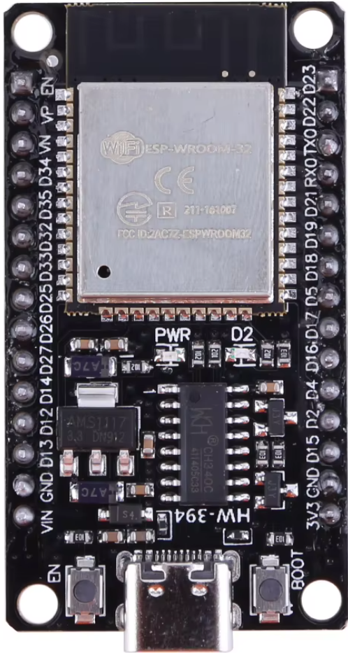
Pin Configuration and Descriptions
The ESP32-WROOM-32D Development Board has a total of 38 pins. Below is a table summarizing the key pin functions:
| Pin Number | Pin Name | Description |
|---|---|---|
| 1 | EN | Reset pin (active high) |
| 2 | GPIO0 | General-purpose I/O, boot mode selection |
| 3 | GPIO1 (TX) | UART0 Transmit |
| 4 | GPIO3 (RX) | UART0 Receive |
| 5 | GPIO4 | General-purpose I/O, PWM capable |
| 6 | GPIO5 | General-purpose I/O, PWM capable |
| 7 | GPIO12 | General-purpose I/O, ADC2 channel |
| 8 | GPIO13 | General-purpose I/O, ADC2 channel |
| 9 | GPIO14 | General-purpose I/O, ADC2 channel |
| 10 | GPIO15 | General-purpose I/O, ADC2 channel |
| 11 | GPIO16 | General-purpose I/O, ADC2 channel |
| 12 | GPIO17 | General-purpose I/O, ADC2 channel |
| 13 | 3V3 | 3.3V power output |
| 14 | GND | Ground |
Note: Not all GPIO pins support all functions simultaneously. Refer to the ESP32 datasheet for detailed pin multiplexing information.
Usage Instructions
How to Use the ESP32-WROOM-32D in a Circuit
Powering the Board:
- Connect the board to a computer or USB power source using a micro-USB cable.
- Alternatively, supply 5V to the VIN pin and connect GND to the ground.
Programming the Board:
- Install the Arduino IDE and add the ESP32 board support package.
- Select "ESP32 Dev Module" from the board manager.
- Connect the board to your computer and upload your code.
Connecting Peripherals:
- Use the GPIO pins to connect sensors, actuators, or other peripherals.
- Ensure that the voltage levels of connected devices are compatible with the 3.3V logic of the ESP32.
Wi-Fi and Bluetooth Setup:
- Use the built-in libraries (
WiFi.handBluetoothSerial.h) to configure wireless communication.
- Use the built-in libraries (
Important Considerations and Best Practices
- Voltage Levels: The GPIO pins operate at 3.3V. Avoid connecting 5V devices directly to the pins without a level shifter.
- Power Supply: Ensure a stable power supply to avoid unexpected resets or performance issues.
- Boot Mode: To enter bootloader mode, hold down the BOOT button while pressing the EN (reset) button.
- Heat Management: The ESP32 can get warm during operation. Ensure proper ventilation if used in enclosed spaces.
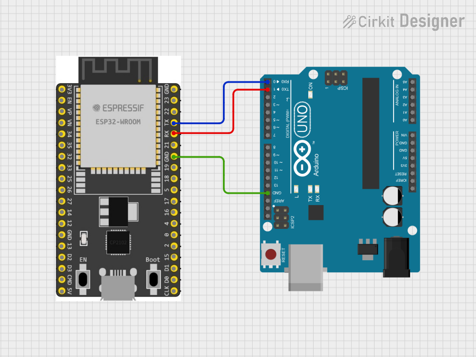
Example Code for Arduino UNO Integration
Below is an example of how to connect the ESP32-WROOM-32D to a Wi-Fi network and send data to a server:
#include <WiFi.h> // Include the Wi-Fi library

// Replace with your network credentials
const char* ssid = "Your_SSID";
const char* password = "Your_PASSWORD";

void setup() {
  Serial.begin(115200); // Initialize serial communication at 115200 baud
  delay(1000);

  // Connect to Wi-Fi
  Serial.println("Connecting to Wi-Fi...");
  WiFi.begin(ssid, password);

  while (WiFi.status() != WL_CONNECTED) {
    delay(500);
    Serial.print("."); // Print dots while connecting
  }

  Serial.println("\nWi-Fi connected!");
  Serial.print("IP Address: ");
  Serial.println(WiFi.localIP()); // Print the assigned IP address
}

void loop() {
  // Add your main code here
}
Tip: Replace
Your_SSIDandYour_PASSWORDwith your Wi-Fi network credentials.
Troubleshooting and FAQs
Common Issues and Solutions
Board Not Detected by Computer:
- Ensure the USB cable is functional and supports data transfer.
- Install the correct USB-to-serial driver for your operating system.
Wi-Fi Connection Fails:
- Double-check the SSID and password.
- Ensure the Wi-Fi network is within range and not using unsupported security protocols.
Code Upload Fails:
- Press and hold the BOOT button while uploading the code.
- Verify that the correct COM port and board type are selected in the Arduino IDE.
Random Resets or Instability:
- Check the power supply for sufficient current (at least 500mA).
- Avoid using GPIO pins connected to the internal flash during boot.
FAQs
Q: Can the ESP32-WROOM-32D operate on battery power?
A: Yes, it can be powered using a 3.7V LiPo battery connected to the VIN and GND pins, but ensure proper voltage regulation.
Q: How do I use Bluetooth on the ESP32?
A: Use the BluetoothSerial library to configure and manage Bluetooth communication.
Q: Can I use the ESP32-WROOM-32D with other IDEs?
A: Yes, the ESP32 is compatible with other IDEs like PlatformIO and Espressif's ESP-IDF.
Q: What is the maximum range of the Wi-Fi module?
A: The Wi-Fi range is approximately 50 meters indoors and up to 200 meters outdoors, depending on environmental factors.
For additional support, refer to the official ESP32 documentation or community forums.