How to Use Breaker Switch: Examples, Pinouts, and Specs
Introduction
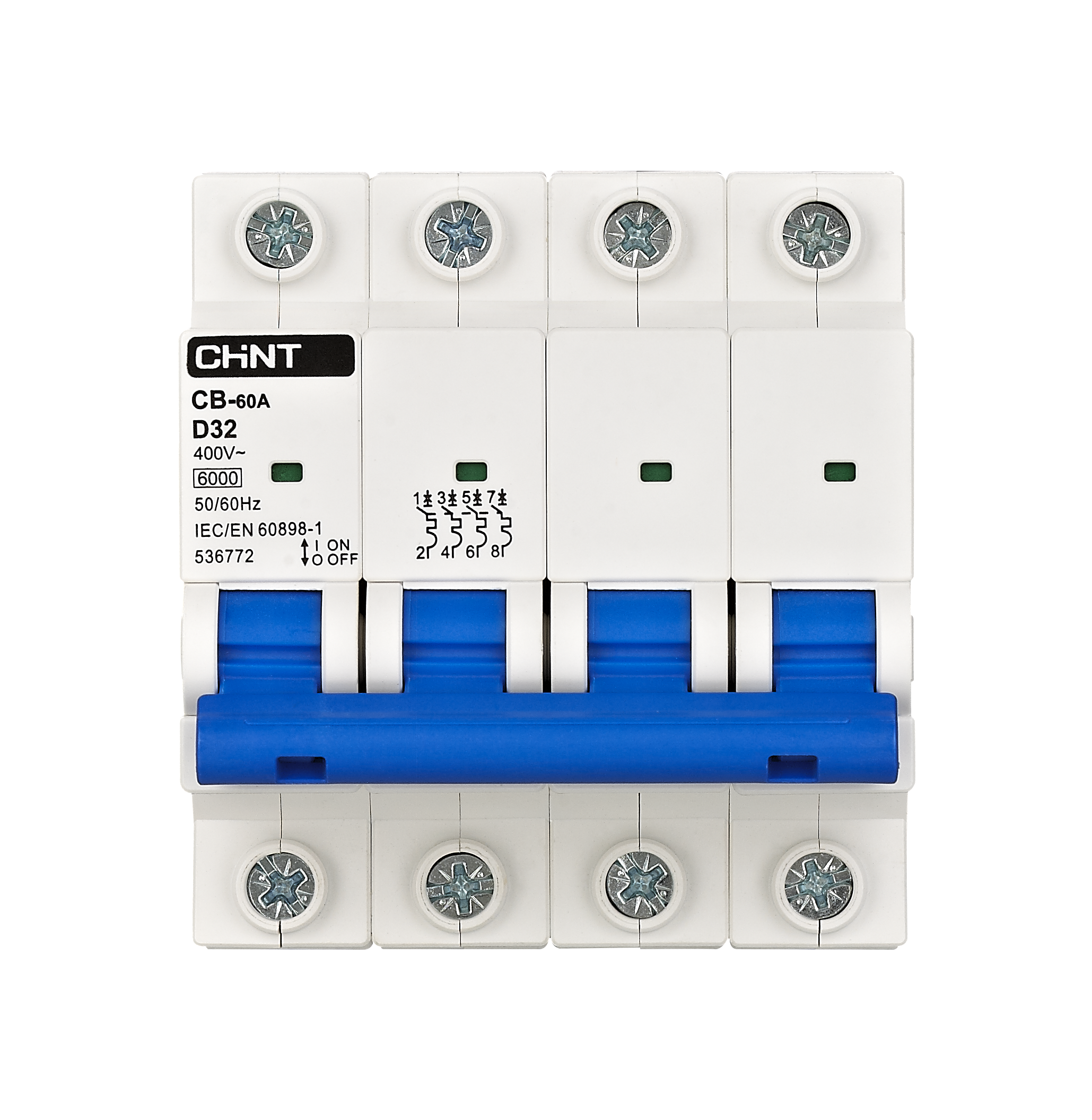
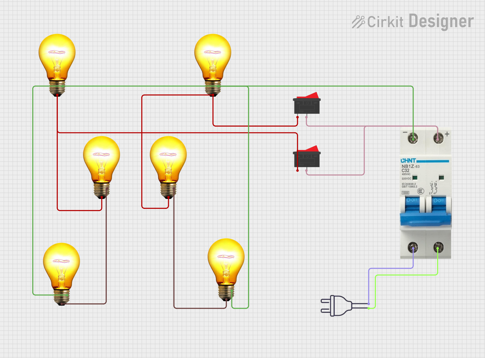
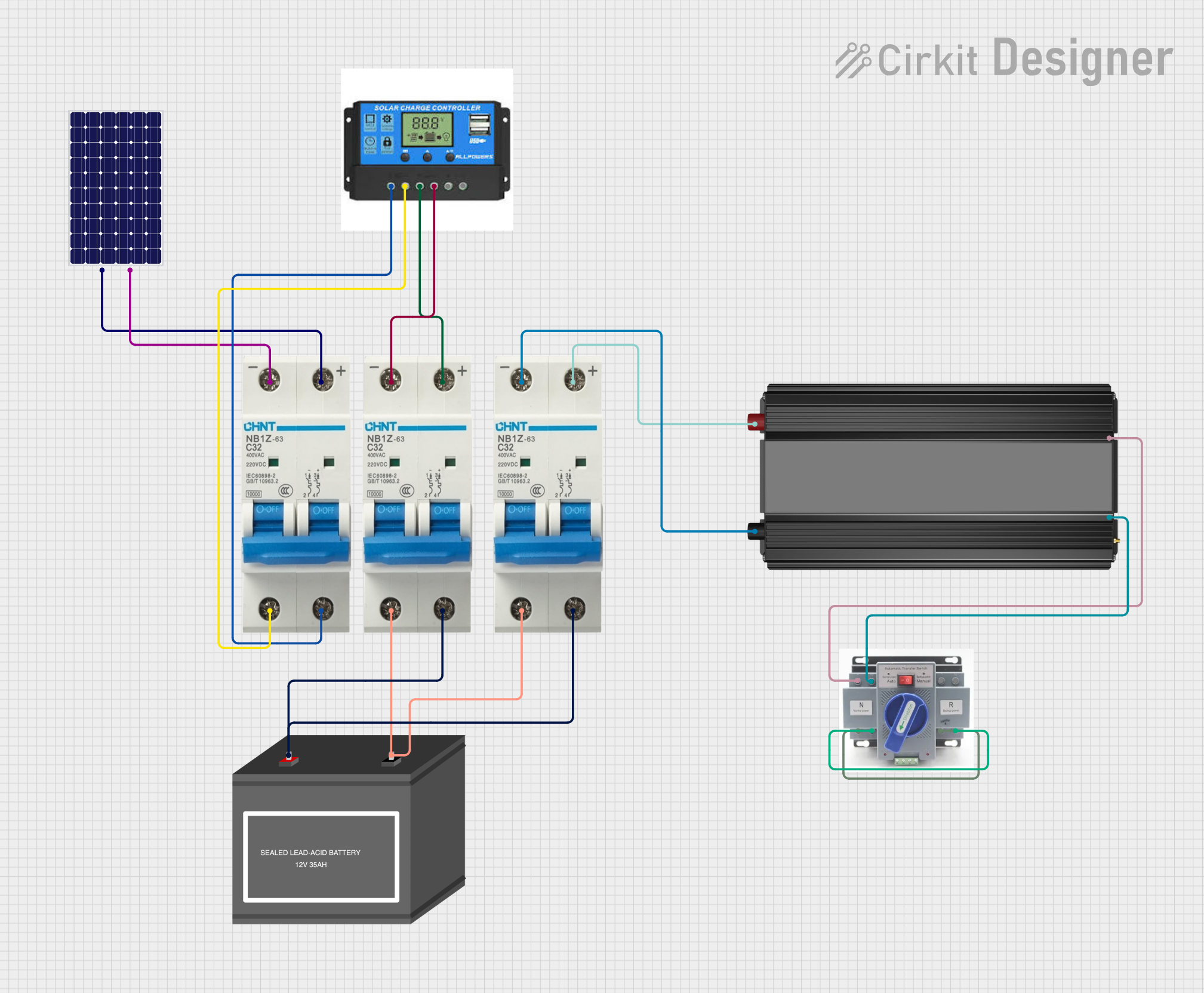
The Breaker Switch (Manufacturer: CHINT, Part ID: Breaker) is an essential safety device designed to automatically interrupt the flow of electricity in a circuit. It protects electrical systems from damage caused by overloads, short circuits, or other electrical faults. By cutting off the current when abnormal conditions are detected, the breaker switch ensures the safety of both the system and its users.
Explore Projects Built with Breaker Switch


Explore Projects Built with Breaker Switch
Common Applications and Use Cases
- Residential, commercial, and industrial electrical systems
- Protection of appliances and equipment from electrical faults
- Circuit isolation for maintenance or repair
- Overload and short circuit protection in power distribution systems
Technical Specifications
The following table outlines the key technical details of the CHINT Breaker Switch:
| Parameter | Specification |
|---|---|
| Rated Voltage | 230V AC / 400V AC |
| Rated Current | 6A, 10A, 16A, 20A, 32A, 40A, 63A |
| Breaking Capacity | 6kA |
| Frequency | 50/60 Hz |
| Number of Poles | 1P, 2P, 3P, 4P |
| Operating Temperature | -5°C to +40°C |
| Mounting Type | DIN Rail |
| Compliance Standards | IEC 60898-1, GB 10963.1 |
Pin Configuration and Descriptions
The breaker switch does not have traditional pins but instead features terminals for connecting input and output wires. The table below describes the terminal configuration:
| Terminal | Description |
|---|---|
| Line (Input) | Connects to the incoming power supply |
| Load (Output) | Connects to the circuit or device to protect |
Usage Instructions
How to Use the Breaker Switch in a Circuit
- Mounting the Breaker: Securely install the breaker switch onto a DIN rail in the distribution box or panel.
- Wiring:
- Connect the Line (Input) terminal to the incoming power supply.
- Connect the Load (Output) terminal to the circuit or device requiring protection.
- Ensure all connections are tight and secure to prevent arcing or loose contacts.
- Testing:
- After installation, switch the breaker to the "ON" position.
- Test the breaker by simulating an overload or short circuit (if safe to do so) to ensure it trips correctly.
- Operation:
- In normal operation, the breaker remains in the "ON" position.
- If a fault occurs, the breaker will trip to the "OFF" position, cutting off the current.
Important Considerations and Best Practices
- Always ensure the breaker’s rated current matches the circuit's requirements.
- Do not exceed the breaker’s breaking capacity (6kA) to avoid damage.
- Regularly inspect the breaker for signs of wear, damage, or overheating.
- Use appropriate tools and safety precautions when installing or servicing the breaker.
- Avoid manually holding the breaker in the "ON" position if it trips repeatedly, as this indicates a persistent fault in the circuit.
Example: Connecting a Breaker Switch to an Arduino UNO
While breaker switches are not directly interfaced with microcontrollers like the Arduino UNO, they can be used in conjunction with relays or sensors to monitor and control power. Below is an example of how to use a relay module to control a circuit protected by a breaker switch:
// Example: Controlling a relay to manage a circuit with a breaker switch
// This code toggles a relay connected to an Arduino UNO, which can control
// the power to a circuit protected by a breaker switch.

const int relayPin = 7; // Pin connected to the relay module

void setup() {
  pinMode(relayPin, OUTPUT); // Set the relay pin as an output
  digitalWrite(relayPin, LOW); // Ensure the relay is off initially
}

void loop() {
  digitalWrite(relayPin, HIGH); // Turn the relay on (circuit powered)
  delay(5000); // Keep the circuit on for 5 seconds
  digitalWrite(relayPin, LOW); // Turn the relay off (circuit disconnected)
  delay(5000); // Keep the circuit off for 5 seconds
}
Note: The breaker switch in this setup provides protection for the circuit, while the relay allows the Arduino to control the power flow.
Troubleshooting and FAQs
Common Issues and Solutions
| Issue | Possible Cause | Solution |
|---|---|---|
| Breaker trips frequently | Overload or short circuit in the circuit | Check the circuit for faults or reduce load |
| Breaker does not trip during a fault | Faulty breaker or incorrect installation | Replace the breaker or verify connections |
| Breaker feels hot to the touch | Loose connections or excessive current | Tighten connections or reduce load |
| Breaker cannot be reset to "ON" | Persistent fault in the circuit | Identify and fix the fault before resetting |
FAQs
Can I use the breaker switch for DC circuits?
- No, this breaker is designed for AC circuits only. Use a DC-rated breaker for DC applications.
What happens if I exceed the rated current of the breaker?
- The breaker will trip to protect the circuit. Repeated overloading may damage the breaker.
How often should I test the breaker?
- It is recommended to test the breaker at least once a year to ensure proper functionality.
Can I use the breaker switch as a regular on/off switch?
- While possible, it is not recommended as frequent manual operation may reduce the lifespan of the breaker.
By following this documentation, users can safely and effectively utilize the CHINT Breaker Switch in their electrical systems.