Cirkit Designer Logo
Cirkit Designer
Your all-in-one circuit design IDE
Home / 
Component Documentation

How to Use nanoESP32-C6 DevKit: Examples, Pinouts, and Specs

Image of nanoESP32-C6 DevKit
Cirkit Designer LogoDesign with nanoESP32-C6 DevKit in Cirkit Designer

Introduction

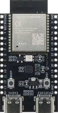
The nanoESP32-C6 DevKit is a compact development board manufactured by MuseLab, featuring the powerful ESP32-C6 chip. This board integrates Wi-Fi 6, Bluetooth 5.0, and IEEE 802.15.4 (Thread/Zigbee) capabilities, making it an ideal choice for IoT applications, smart home devices, and wireless communication projects. Its small form factor and robust features make it suitable for rapid prototyping and deployment in space-constrained environments.

Explore Projects Built with nanoESP32-C6 DevKit

Use Cirkit Designer to design, explore, and prototype these projects online. Some projects support real-time simulation. Click "Open Project" to start designing instantly!
ESP32-Based Smart Agriculture System with LoRa Communication
Image of Soil Monitoring Device: A project utilizing nanoESP32-C6 DevKit in a practical application
This circuit features an ESP32 Devkit V1 microcontroller as the central processing unit, interfacing with various sensors including a PH Meter, an NPK Soil Sensor, and a Soil Moisture Sensor for environmental data collection. It also includes an EBYTE LoRa E220 module for wireless communication. Power management is handled by a Step Up Boost Power Converter, which is connected to a 12V Battery, stepping up the voltage to power the ESP32 and sensors, with common ground connections throughout the circuit.
Cirkit Designer LogoOpen Project in Cirkit Designer
ESP32-Based GPS Tracker with Serial Communication
Image of Smart Helmet: A project utilizing nanoESP32-C6 DevKit in a practical application
This circuit connects a GPS NEO 6M module to an ESP32 Devkit V1 microcontroller. The ESP32 powers the GPS module and communicates with it via serial connection, using its RX0 and TX0 pins to receive and transmit data. The embedded code on the ESP32 is configured to read GPS data such as latitude, longitude, and altitude, and output this information to the serial monitor.
Cirkit Designer LogoOpen Project in Cirkit Designer
Battery-Powered GPS Tracker with ESP32 and NEO 6M
Image of SeekPeek: A project utilizing nanoESP32-C6 DevKit in a practical application
This circuit is a GPS tracking system powered by a 3.7V battery, which is charged via a TP4056 module. The ESP32 Devkit V1 microcontroller interfaces with the GPS NEO 6M module to receive location data, which can be processed and transmitted as needed.
Cirkit Designer LogoOpen Project in Cirkit Designer
ESP32-Based Environmental Monitoring and Alert System with Solar Charging
Image of mark: A project utilizing nanoESP32-C6 DevKit in a practical application
This circuit features an ESP32 Devkit V1 microcontroller connected to various sensors and modules for monitoring and communication purposes. It includes an MQ-2 gas sensor and a DHT11 temperature and humidity sensor, both interfaced with the ESP32 for environmental data collection. The circuit is powered by a 12V battery, regulated to 5V by step-down converters, and includes a solar charge controller connected to a solar panel for battery charging, a UPS module for power management, and a SIM900A module for GSM communication. Additionally, there is a WS2812 RGB LED strip for visual feedback and a piezo buzzer for audio alerts, both controlled by the ESP32.
Cirkit Designer LogoOpen Project in Cirkit Designer

Explore Projects Built with nanoESP32-C6 DevKit

Use Cirkit Designer to design, explore, and prototype these projects online. Some projects support real-time simulation. Click "Open Project" to start designing instantly!
Image of Soil Monitoring Device: A project utilizing nanoESP32-C6 DevKit in a practical application
ESP32-Based Smart Agriculture System with LoRa Communication
This circuit features an ESP32 Devkit V1 microcontroller as the central processing unit, interfacing with various sensors including a PH Meter, an NPK Soil Sensor, and a Soil Moisture Sensor for environmental data collection. It also includes an EBYTE LoRa E220 module for wireless communication. Power management is handled by a Step Up Boost Power Converter, which is connected to a 12V Battery, stepping up the voltage to power the ESP32 and sensors, with common ground connections throughout the circuit.
Cirkit Designer LogoOpen Project in Cirkit Designer
Image of Smart Helmet: A project utilizing nanoESP32-C6 DevKit in a practical application
ESP32-Based GPS Tracker with Serial Communication
This circuit connects a GPS NEO 6M module to an ESP32 Devkit V1 microcontroller. The ESP32 powers the GPS module and communicates with it via serial connection, using its RX0 and TX0 pins to receive and transmit data. The embedded code on the ESP32 is configured to read GPS data such as latitude, longitude, and altitude, and output this information to the serial monitor.
Cirkit Designer LogoOpen Project in Cirkit Designer
Image of SeekPeek: A project utilizing nanoESP32-C6 DevKit in a practical application
Battery-Powered GPS Tracker with ESP32 and NEO 6M
This circuit is a GPS tracking system powered by a 3.7V battery, which is charged via a TP4056 module. The ESP32 Devkit V1 microcontroller interfaces with the GPS NEO 6M module to receive location data, which can be processed and transmitted as needed.
Cirkit Designer LogoOpen Project in Cirkit Designer
Image of mark: A project utilizing nanoESP32-C6 DevKit in a practical application
ESP32-Based Environmental Monitoring and Alert System with Solar Charging
This circuit features an ESP32 Devkit V1 microcontroller connected to various sensors and modules for monitoring and communication purposes. It includes an MQ-2 gas sensor and a DHT11 temperature and humidity sensor, both interfaced with the ESP32 for environmental data collection. The circuit is powered by a 12V battery, regulated to 5V by step-down converters, and includes a solar charge controller connected to a solar panel for battery charging, a UPS module for power management, and a SIM900A module for GSM communication. Additionally, there is a WS2812 RGB LED strip for visual feedback and a piezo buzzer for audio alerts, both controlled by the ESP32.
Cirkit Designer LogoOpen Project in Cirkit Designer

Common Applications and Use Cases

  • IoT devices and smart home automation
  • Wireless sensor networks
  • Bluetooth-enabled devices
  • Zigbee/Thread-based communication systems
  • Low-power, high-performance embedded systems

Technical Specifications

Below are the key technical details and pin configuration for the nanoESP32-C6 DevKit:

Key Technical Details

Parameter Specification
Chipset ESP32-C6
Wi-Fi Wi-Fi 6 (802.11ax), 2.4 GHz
Bluetooth Bluetooth 5.0 (LE)
Zigbee/Thread IEEE 802.15.4
Operating Voltage 3.3V
Input Voltage Range 5V (via USB-C)
Flash Memory 4 MB
SRAM 512 KB
GPIO Pins 14
Communication Interfaces UART, SPI, I2C, I2S, PWM
Power Consumption Ultra-low power mode supported
Dimensions 18 mm x 45 mm

Pin Configuration and Descriptions

Pin Number Pin Name Description
1 GND Ground
2 3V3 3.3V Power Output
3 EN Enable Pin (Active High)
4 IO0 GPIO0, Boot Mode Selection
5 IO1 GPIO1, General Purpose I/O
6 IO2 GPIO2, General Purpose I/O
7 IO3 GPIO3, General Purpose I/O
8 IO4 GPIO4, General Purpose I/O
9 IO5 GPIO5, General Purpose I/O
10 RXD UART Receive
11 TXD UART Transmit
12 SCL I2C Clock Line
13 SDA I2C Data Line
14 RST Reset Pin

Usage Instructions

How to Use the Component in a Circuit

  1. Powering the Board:

    • Connect the nanoESP32-C6 DevKit to a 5V power source using the USB-C port. The onboard voltage regulator will step down the voltage to 3.3V for the ESP32-C6 chip.
    • Alternatively, you can power the board directly via the 3V3 pin.
  2. Programming the Board:

    • Use the Arduino IDE or ESP-IDF (Espressif IoT Development Framework) to program the board.
    • Select the appropriate board type (ESP32-C6) and port in the IDE settings.
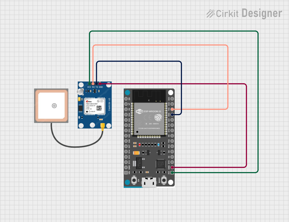
  3. Connecting Peripherals:

    • Use the GPIO pins to connect sensors, actuators, or other peripherals. Ensure that the voltage levels of connected devices are compatible with the 3.3V logic of the board.
  4. Wireless Communication:

    • Configure Wi-Fi, Bluetooth, or Zigbee/Thread communication using the appropriate libraries and APIs provided by Espressif.

Important Considerations and Best Practices

  • Voltage Levels: Ensure all connected peripherals operate at 3.3V logic levels to avoid damaging the board.
  • Boot Mode: To enter bootloader mode, hold the IO0 pin low while resetting the board.
  • Antenna Placement: Avoid placing metallic objects near the onboard antenna to ensure optimal wireless performance.
  • Power Consumption: Use the ultra-low power mode for battery-powered applications to extend battery life.

Example Code for Arduino UNO Integration

Below is an example of using the nanoESP32-C6 DevKit to connect to a Wi-Fi network and send data to a server:

#include <WiFi.h> // Include the Wi-Fi library

// Replace with your network credentials
const char* ssid = "Your_SSID";
const char* password = "Your_PASSWORD";

void setup() {
  Serial.begin(115200); // Initialize serial communication
  delay(1000);

  // Connect to Wi-Fi
  Serial.print("Connecting to Wi-Fi");
  WiFi.begin(ssid, password);
  while (WiFi.status() != WL_CONNECTED) {
    delay(500);
    Serial.print(".");
  }
  Serial.println("\nConnected to Wi-Fi!");
  Serial.print("IP Address: ");
  Serial.println(WiFi.localIP()); // Print the device's IP address
}

void loop() {
  // Add your main code here
}

Troubleshooting and FAQs

Common Issues and Solutions

  1. Board Not Detected by IDE:

    • Ensure the correct USB driver is installed for the nanoESP32-C6 DevKit.
    • Verify that the USB cable is functional and supports data transfer.
  2. Wi-Fi Connection Fails:

    • Double-check the SSID and password for your Wi-Fi network.
    • Ensure the Wi-Fi network operates on the 2.4 GHz band, as the ESP32-C6 does not support 5 GHz.
  3. GPIO Pins Not Responding:

    • Verify that the pins are not being used for other functions (e.g., boot mode).
    • Check for short circuits or incorrect wiring.
  4. High Power Consumption:

    • Enable the ultra-low power mode in your code for battery-powered applications.
    • Disconnect unused peripherals to reduce power draw.

FAQs

Q: Can I use the nanoESP32-C6 DevKit with Zigbee devices?
A: Yes, the board supports IEEE 802.15.4, which is compatible with Zigbee and Thread protocols.

Q: What is the maximum Wi-Fi range of the board?
A: The range depends on environmental factors, but typically it can reach up to 50 meters indoors and 200 meters outdoors.

Q: Does the board support OTA (Over-the-Air) updates?
A: Yes, the ESP32-C6 chip supports OTA updates, allowing you to update firmware wirelessly.

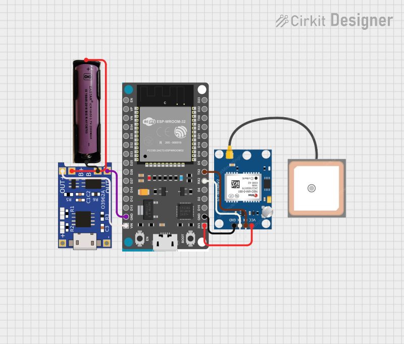
Q: Can I power the board using a battery?
A: Yes, you can use a 3.7V LiPo battery with a suitable voltage regulator to provide 3.3V to the board.

Q: Is the board compatible with Arduino libraries?
A: Yes, the nanoESP32-C6 DevKit is compatible with most Arduino libraries for ESP32-based devices.