How to Use VOLTAGE DETECTOR: Examples, Pinouts, and Specs
Introduction
A voltage detector is a device used to sense the presence of voltage in a circuit. It can indicate whether a circuit is live or not, often through visual or audible signals. Voltage detectors are commonly used for safety in electrical work, helping users identify live circuits before performing maintenance or repairs. They are essential tools for electricians, engineers, and hobbyists working with electrical systems.
Explore Projects Built with VOLTAGE DETECTOR
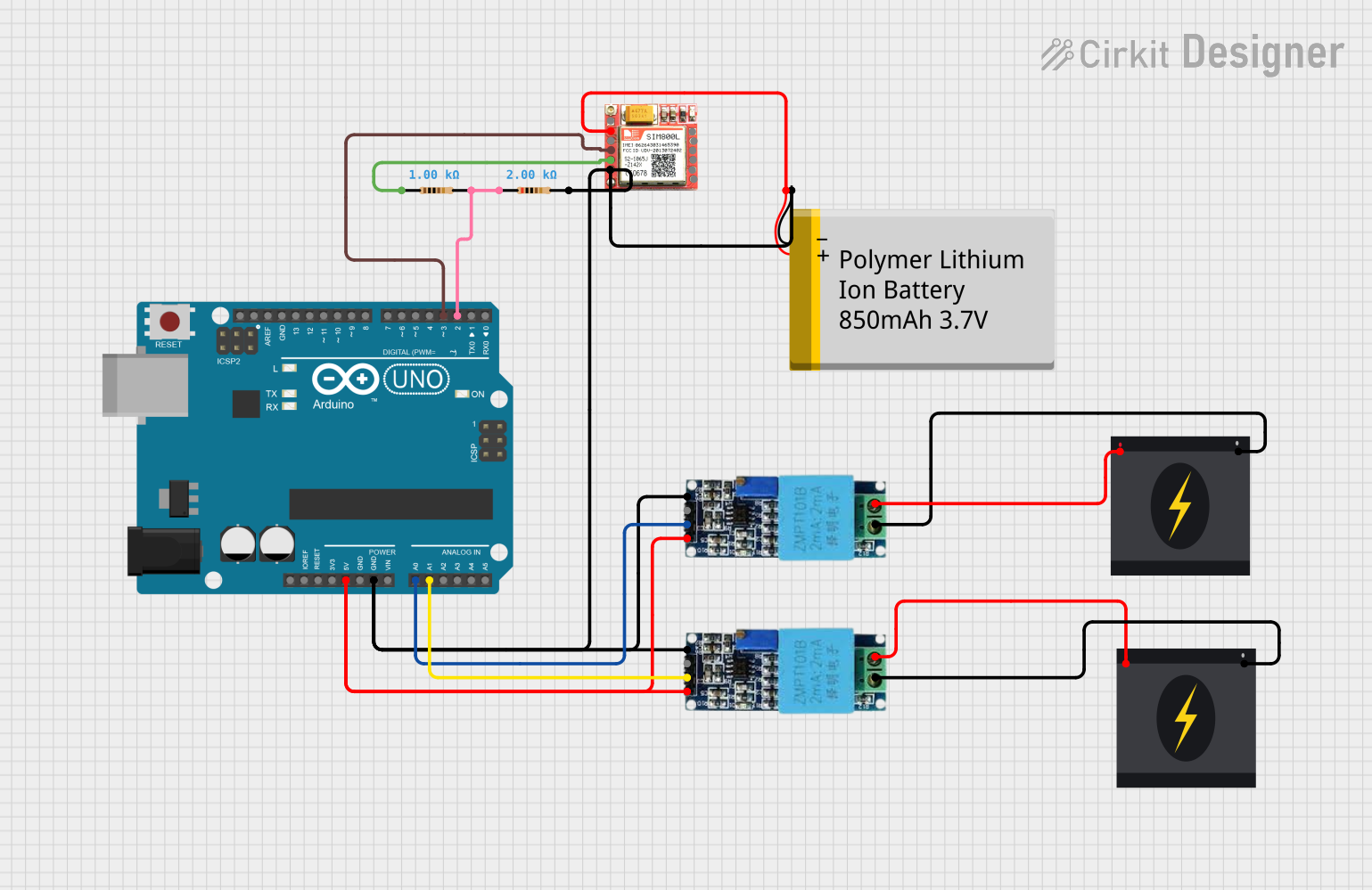
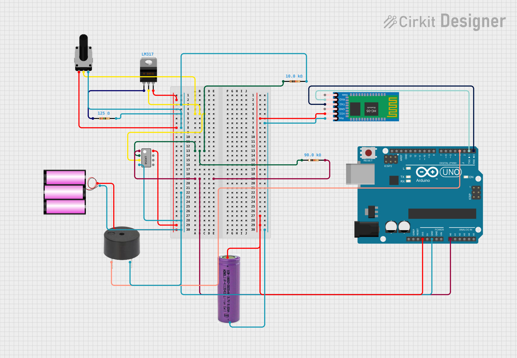
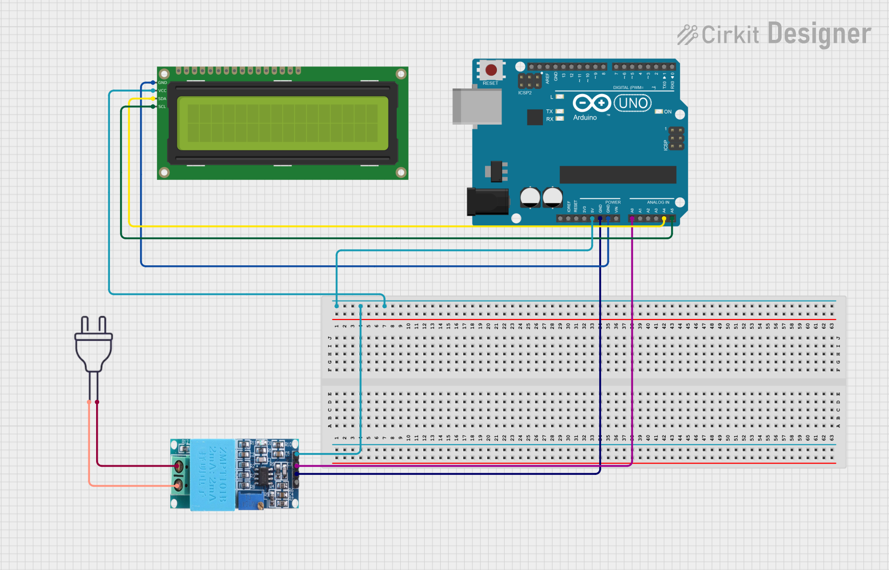
Explore Projects Built with VOLTAGE DETECTOR
Common Applications and Use Cases
- Identifying live wires in electrical installations
- Testing for voltage presence in outlets, switches, and circuit breakers
- Ensuring safety during electrical repairs or maintenance
- Troubleshooting electrical circuits in appliances and devices
- Educational purposes in electronics labs
Technical Specifications
Below are the general technical specifications for a typical voltage detector. Note that specific models may vary slightly in their ratings and features.
| Parameter | Specification |
|---|---|
| Operating Voltage Range | 12V to 1000V AC (typical) |
| Detection Method | Non-contact (capacitive sensing) |
| Indication Type | LED light and/or audible buzzer |
| Power Supply | 2x AAA batteries (1.5V each) |
| Frequency Range | 50Hz to 60Hz |
| Operating Temperature | -10°C to 50°C |
| Storage Temperature | -20°C to 60°C |
| Dimensions | Varies (e.g., 150mm x 20mm x 20mm) |
| Weight | Approximately 50g |
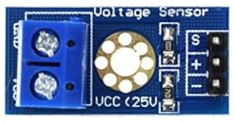
Pin Configuration and Descriptions
Voltage detectors are typically standalone devices and do not have pins for integration into circuits. However, if the voltage detector is part of a module or IC, the pin configuration may look like the following:
| Pin Name | Description |
|---|---|
| VCC | Power supply input (e.g., 3.3V or 5V) |
| GND | Ground connection |
| OUT | Output signal pin (indicates voltage detection) |
Usage Instructions
How to Use the Component in a Circuit
Standalone Voltage Detector:
- Turn on the voltage detector by pressing the power button or sliding the switch.
- Hold the detector near the wire or circuit you want to test.
- If voltage is present, the detector will emit a visual (LED) and/or audible (buzzer) signal.
- Ensure the detector is within its specified voltage range for accurate results.
Voltage Detector Module (for circuits):
- Connect the
VCCpin to the power supply (e.g., 3.3V or 5V). - Connect the
GNDpin to the ground of your circuit. - Use the
OUTpin to monitor the detection signal. This pin typically outputs a HIGH signal when voltage is detected.
- Connect the
Important Considerations and Best Practices
- Always verify the voltage detector's operating range before use to avoid damage or inaccurate readings.
- For non-contact detectors, ensure the device is close enough to the wire or circuit for proper sensing.
- Avoid using the detector in wet or humid environments unless it is rated for such conditions.
- Replace the batteries regularly to ensure consistent performance.
- When using a voltage detector module with a microcontroller (e.g., Arduino), ensure proper voltage level compatibility.
Example: Using a Voltage Detector Module with Arduino UNO
Below is an example of how to use a voltage detector module with an Arduino UNO to monitor voltage presence and trigger an LED.
// Define the pin connections
const int voltageDetectorPin = 2; // Input pin connected to OUT of the module
const int ledPin = 13;            // Built-in LED on Arduino UNO

void setup() {
  pinMode(voltageDetectorPin, INPUT); // Set the detector pin as input
  pinMode(ledPin, OUTPUT);           // Set the LED pin as output
  Serial.begin(9600);                // Initialize serial communication
}

void loop() {
  int voltageDetected = digitalRead(voltageDetectorPin); // Read the detector output

  if (voltageDetected == HIGH) {
    digitalWrite(ledPin, HIGH); // Turn on the LED if voltage is detected
    Serial.println("Voltage detected!"); // Print message to serial monitor
  } else {
    digitalWrite(ledPin, LOW); // Turn off the LED if no voltage is detected
    Serial.println("No voltage detected."); // Print message to serial monitor
  }

  delay(500); // Wait for 500ms before the next reading
}
Troubleshooting and FAQs
Common Issues Users Might Face
Voltage Detector Not Responding:
- Ensure the batteries are properly installed and have sufficient charge.
- Verify that the detector is within its specified operating voltage range.
False Positives or Noisy Signals:
- Check for nearby electromagnetic interference (EMI) that may affect the detector.
- Ensure the detector is not too far from the voltage source.
No Output from Voltage Detector Module:
- Verify the connections to the
VCC,GND, andOUTpins. - Ensure the module is powered with the correct voltage level.
- Verify the connections to the
Arduino Code Not Working:
- Double-check the pin connections between the Arduino and the voltage detector module.
- Ensure the correct pin number is defined in the code.
Solutions and Tips for Troubleshooting
- Test the voltage detector on a known live circuit to confirm it is functioning correctly.
- Replace the batteries if the detector's LED or buzzer is weak or unresponsive.
- For modules, use a multimeter to verify the output signal on the
OUTpin. - If using with an Arduino, use the serial monitor to debug the output readings.
By following these guidelines and troubleshooting tips, you can effectively use a voltage detector for a variety of applications.