
How to Use 12V VOLTAGE DETECTOR: Examples, Pinouts, and Specs
 Design with 12V VOLTAGE DETECTOR in Cirkit Designer
Introduction
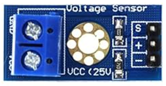
The 12V Voltage Detector is a compact and reliable device designed to monitor and indicate the presence of a 12V voltage level in a circuit. It is commonly used in automotive, industrial, and electronic applications to ensure safety and verify operational conditions. This component is particularly useful for detecting power supply issues, monitoring battery levels, and providing visual or audible alerts when a 12V voltage is present or absent.
Explore Projects Built with 12V VOLTAGE DETECTOR
 Open Project in Cirkit Designer
 Open Project in Cirkit Designer
 Open Project in Cirkit Designer
 Open Project in Cirkit Designer
Explore Projects Built with 12V VOLTAGE DETECTOR
Open Project in Cirkit DesignerOpen Project in Cirkit DesignerOpen Project in Cirkit DesignerOpen Project in Cirkit DesignerCommon Applications
- Automotive systems to monitor battery voltage
- Industrial equipment for power supply verification
- DIY electronics projects for voltage detection
- Safety systems to ensure proper voltage levels in circuits
Technical Specifications
The following table outlines the key technical details of the 12V Voltage Detector:
| Parameter | Value |
|---|---|
| Operating Voltage | 12V DC |
| Voltage Detection Range | 10V to 14V DC |
| Output Type | LED indicator or digital pin |
| Current Consumption | ≤ 10mA |
| Operating Temperature | -20°C to 70°C |
| Dimensions | Varies by model (e.g., 20x10mm) |
Pin Configuration
The 12V Voltage Detector typically has three pins. The table below describes the pinout:
| Pin | Name | Description |
|---|---|---|
| 1 | VCC | Connect to the positive 12V DC supply |
| 2 | GND | Connect to the ground of the circuit |
| 3 | OUT | Output pin that indicates the presence of 12V (HIGH) |
Usage Instructions
How to Use the 12V Voltage Detector in a Circuit
- Power Connection: Connect the
VCCpin to the 12V DC power supply and theGNDpin to the ground of the circuit. - Output Monitoring: Use the
OUTpin to monitor the voltage status:- When 12V is detected, the
OUTpin will output a HIGH signal (or activate an LED indicator). - When the voltage drops below the detection threshold, the
OUTpin will output a LOW signal.
- When 12V is detected, the
- Load Connection: If the detector includes an LED indicator, ensure it is visible for monitoring. For digital output, connect the
OUTpin to a microcontroller or external circuit for further processing.
Important Considerations
- Ensure the input voltage does not exceed the specified range (10V to 14V) to avoid damage.
- Use appropriate resistors if connecting the
OUTpin to a microcontroller to limit current. - Avoid exposing the detector to extreme temperatures or moisture to maintain reliability.
Example: Connecting to an Arduino UNO
The 12V Voltage Detector can be interfaced with an Arduino UNO to monitor the voltage status and trigger actions based on the detection. Below is an example code snippet:
// Define the pin connected to the OUT pin of the 12V Voltage Detector
const int voltageDetectorPin = 2; // Digital pin 2 on Arduino UNO

void setup() {
  pinMode(voltageDetectorPin, INPUT); // Set the pin as input
  Serial.begin(9600); // Initialize serial communication for debugging
}

void loop() {
  int voltageStatus = digitalRead(voltageDetectorPin); // Read the detector output

  if (voltageStatus == HIGH) {
    // If 12V is detected, print a message
    Serial.println("12V detected in the circuit.");
  } else {
    // If 12V is not detected, print a warning
    Serial.println("12V not detected. Check the power supply.");
  }

  delay(1000); // Wait for 1 second before checking again
}
Troubleshooting and FAQs
Common Issues and Solutions
The LED Indicator Does Not Light Up
- Cause: The input voltage is below the detection threshold.
- Solution: Verify the input voltage using a multimeter and ensure it is within the 10V to 14V range.
No Output Signal on the OUT Pin
- Cause: Incorrect wiring or damaged component.
- Solution: Double-check the connections to the
VCC,GND, andOUTpins. Replace the detector if necessary.
Intermittent Detection
- Cause: Fluctuating input voltage or loose connections.
- Solution: Stabilize the power supply and secure all connections.
FAQs
Q: Can the 12V Voltage Detector be used with voltages higher than 12V?
A: No, the detector is designed for a specific range (10V to 14V). Using higher voltages may damage the component.
Q: Is the detector compatible with 3.3V microcontrollers?
A: Yes, but you may need a level shifter or resistor divider to safely interface the OUT pin with the microcontroller.
Q: Can I use the detector for AC voltage?
A: No, the 12V Voltage Detector is designed for DC voltage only. Using it with AC voltage may result in incorrect readings or damage.
By following this documentation, you can effectively integrate and troubleshoot the 12V Voltage Detector in your projects.