How to Use 0V7670 Camera Module (no FIFO): Examples, Pinouts, and Specs
OV7670 Camera Module (No FIFO) Documentation
1. Introduction
The OV7670 Camera Module is a compact and cost-effective imaging solution designed for capturing images and video. It features a resolution of 640x480 pixels (VGA) and supports various image formats such as RGB565, YUV422, and more. Unlike its FIFO-equipped counterparts, this module streams data directly to the processor, making it ideal for real-time image processing applications.
Common Applications
- Robotics: Object detection and tracking
- Surveillance: Low-cost video monitoring systems
- IoT Projects: Image capture for smart devices
- Embedded Systems: Real-time image processing
- DIY Projects: Integration with microcontrollers like Arduino and Raspberry Pi
The absence of a FIFO buffer requires the host processor to handle data in real time, making it more challenging to use but also more flexible for advanced applications.
2. Technical Specifications
Key Technical Details
| Parameter | Value |
|---|---|
| Resolution | 640x480 pixels (VGA) |
| Image Formats | RGB565, YUV422, Bayer RAW |
| Operating Voltage | 3.3V (logic level) |
| Power Consumption | ~60mW |
| Clock Input | 24 MHz (external oscillator) |
| Frame Rate | Up to 30 fps (VGA) |
| Communication Interface | Parallel (8-bit data bus) |
| Lens | Fixed focus |
| Operating Temperature | -30°C to 70°C |
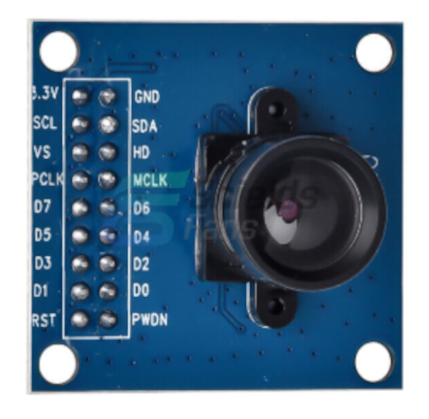
Pin Configuration and Descriptions
| Pin Name | Pin Number | Description |
|---|---|---|
| VCC | 1 | Power supply (3.3V) |
| GND | 2 | Ground |
| SCL | 3 | I2C clock line for configuration |
| SDA | 4 | I2C data line for configuration |
| D0-D7 | 5-12 | 8-bit parallel data output (D0 = LSB, D7 = MSB) |
| PCLK | 13 | Pixel clock output (synchronizes data transfer) |
| VSYNC | 14 | Vertical sync signal (indicates the start of a new frame) |
| HREF | 15 | Horizontal reference signal (indicates valid data on the data bus) |
| XCLK | 16 | External clock input (24 MHz required) |
| RESET | 17 | Active-low reset pin (optional, can be tied to VCC if not used) |
| PWDN | 18 | Power-down mode (active high, optional, can be tied to GND if not used) |
3. Usage Instructions
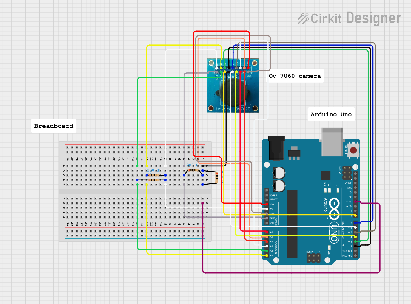
Connecting the OV7670 to an Arduino UNO
The OV7670 Camera Module requires a microcontroller capable of handling its parallel data output. The Arduino UNO, with its limited memory and processing power, can only handle low-resolution images or specific portions of the frame. Below is a basic guide to connect the module to the Arduino UNO:
Wiring Diagram
| OV7670 Pin | Arduino Pin | Description |
|---|---|---|
| VCC | 3.3V | Power supply |
| GND | GND | Ground |
| SCL | A5 | I2C clock |
| SDA | A4 | I2C data |
| D0-D7 | Digital Pins 2-9 | Parallel data bus (D0 = Pin 2, etc.) |
| PCLK | Digital Pin 11 | Pixel clock |
| VSYNC | Digital Pin 12 | Vertical sync |
| HREF | Digital Pin 13 | Horizontal reference |
| XCLK | Digital Pin 3 | External clock input (via PWM) |
| RESET | 3.3V | Tied to VCC (optional) |
| PWDN | GND | Tied to GND (optional) |
Sample Arduino Code
The following code demonstrates how to initialize the OV7670 module and capture basic data. Note that due to the Arduino UNO's limited memory, this example focuses on configuration and basic communication.
#include <Wire.h> // Include the I2C library for communication

// OV7670 I2C address
#define OV7670_I2C_ADDR 0x42

// Function to write a register value to the OV7670
void writeRegister(uint8_t reg, uint8_t value) {
  Wire.beginTransmission(OV7670_I2C_ADDR >> 1); // Start I2C communication
  Wire.write(reg); // Send the register address
  Wire.write(value); // Send the value to write
  Wire.endTransmission(); // End I2C communication
}

void setup() {
  Wire.begin(); // Initialize I2C
  Serial.begin(9600); // Initialize serial communication for debugging

  // Configure the OV7670 registers
  writeRegister(0x12, 0x80); // Reset all registers
  delay(100); // Wait for reset to complete

  // Set VGA resolution and RGB565 format
  writeRegister(0x12, 0x14); // Set RGB565 and VGA mode
  writeRegister(0x11, 0x01); // Set clock prescaler for frame rate

  Serial.println("OV7670 initialized!");
}

void loop() {
  // OV7670 data handling would go here
  // For example, reading pixel data from the D0-D7 pins
}
Important Considerations
- Clock Signal: The OV7670 requires a 24 MHz clock signal on the XCLK pin. This can be generated using the Arduino's PWM functionality or an external oscillator.
- Memory Limitations: The Arduino UNO has only 2 KB of SRAM, which is insufficient for storing full VGA frames. Consider using a microcontroller with more memory (e.g., ESP32) for advanced applications.
- Voltage Levels: The OV7670 operates at 3.3V logic levels. Use level shifters if interfacing with a 5V microcontroller.
4. Troubleshooting and FAQs
Common Issues and Solutions
| Issue | Possible Cause | Solution |
|---|---|---|
| No image output | Incorrect wiring or configuration | Double-check connections and register settings. |
| Distorted or noisy image | Clock signal instability | Ensure a stable 24 MHz clock signal on the XCLK pin. |
| Arduino resets or crashes | Insufficient memory | Reduce resolution or use a microcontroller with more memory (e.g., ESP32). |
| Module not responding to I2C commands | Incorrect I2C address or wiring | Verify the I2C address (0x42) and check SDA/SCL connections. |
| Image too dark or too bright | Incorrect exposure or gain settings | Adjust the relevant registers (e.g., 0x13 for auto-gain control). |
FAQs
Can the OV7670 capture video?
- Yes, the OV7670 can capture video at up to 30 fps, but the host processor must handle the data in real time.
Why is there no FIFO buffer?
- The absence of a FIFO buffer reduces cost and complexity but requires the host processor to handle data directly.
Can I use the OV7670 with a Raspberry Pi?
- Yes, the OV7670 can be used with a Raspberry Pi, which has sufficient processing power and memory for handling image data.
What microcontrollers are recommended for the OV7670?
- While the Arduino UNO can be used for basic tasks, microcontrollers like the ESP32 or STM32 are better suited for handling the OV7670's data output.
This documentation provides a comprehensive guide to using the OV7670 Camera Module (No FIFO). For advanced applications, consider exploring additional resources and libraries tailored to your specific microcontroller platform.
Explore Projects Built with 0V7670 Camera Module (no FIFO)
Explore Projects Built with 0V7670 Camera Module (no FIFO)