How to Use Wattmeter: Examples, Pinouts, and Specs
Introduction
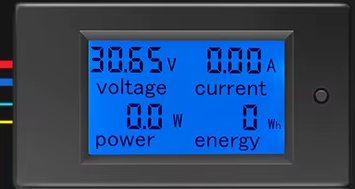
The PZEM-051 Wattmeter is an electrical instrument designed to measure the power of an electrical circuit in watts. It is capable of measuring both AC and DC power, making it a versatile tool for monitoring energy consumption and efficiency. This wattmeter is widely used in applications such as energy monitoring, power system analysis, and load testing. Its compact design and ease of integration make it suitable for both industrial and hobbyist projects.
Explore Projects Built with Wattmeter
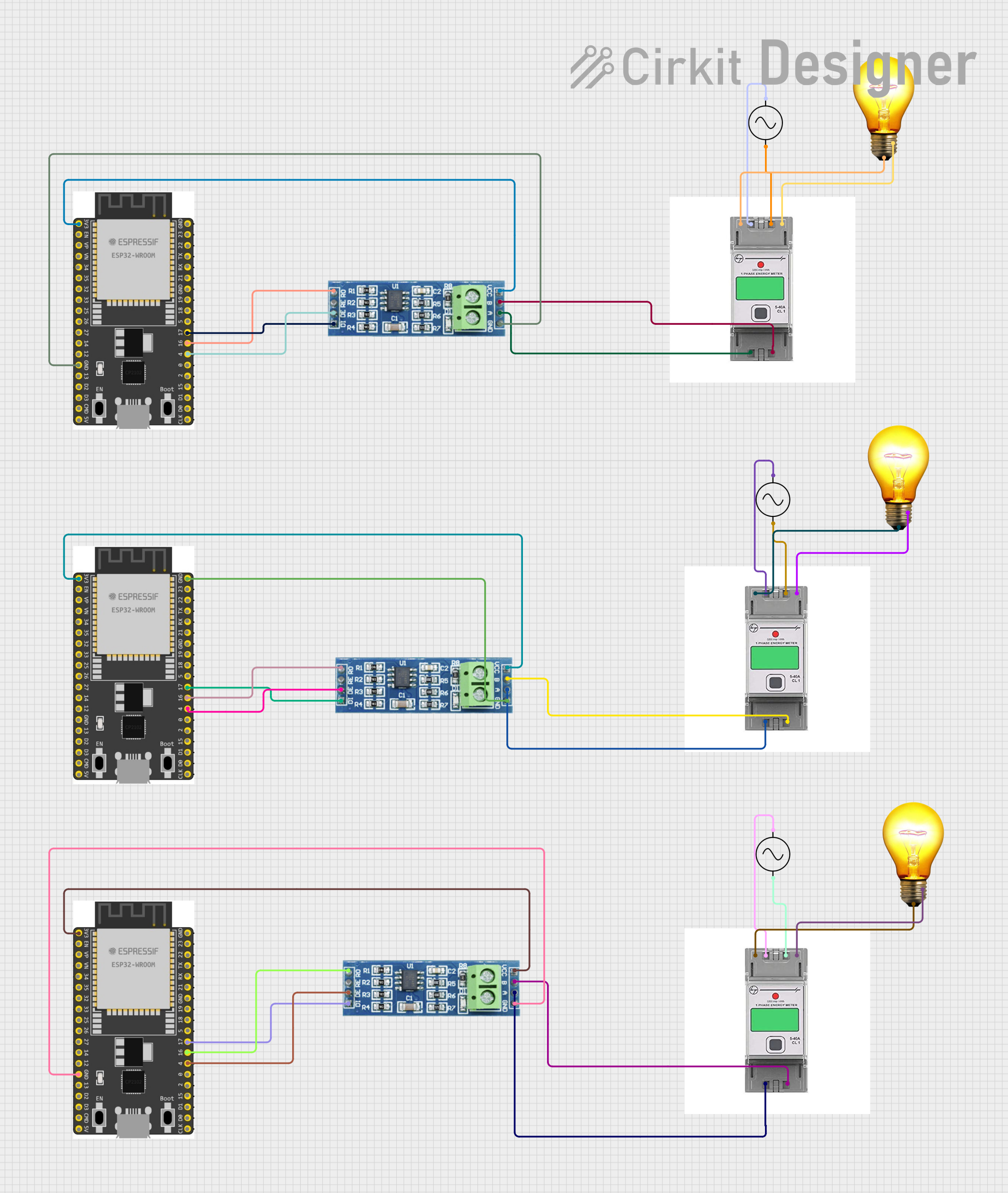
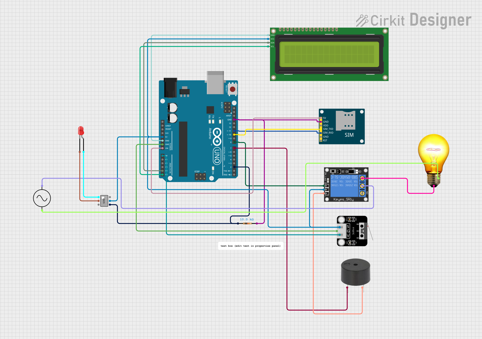
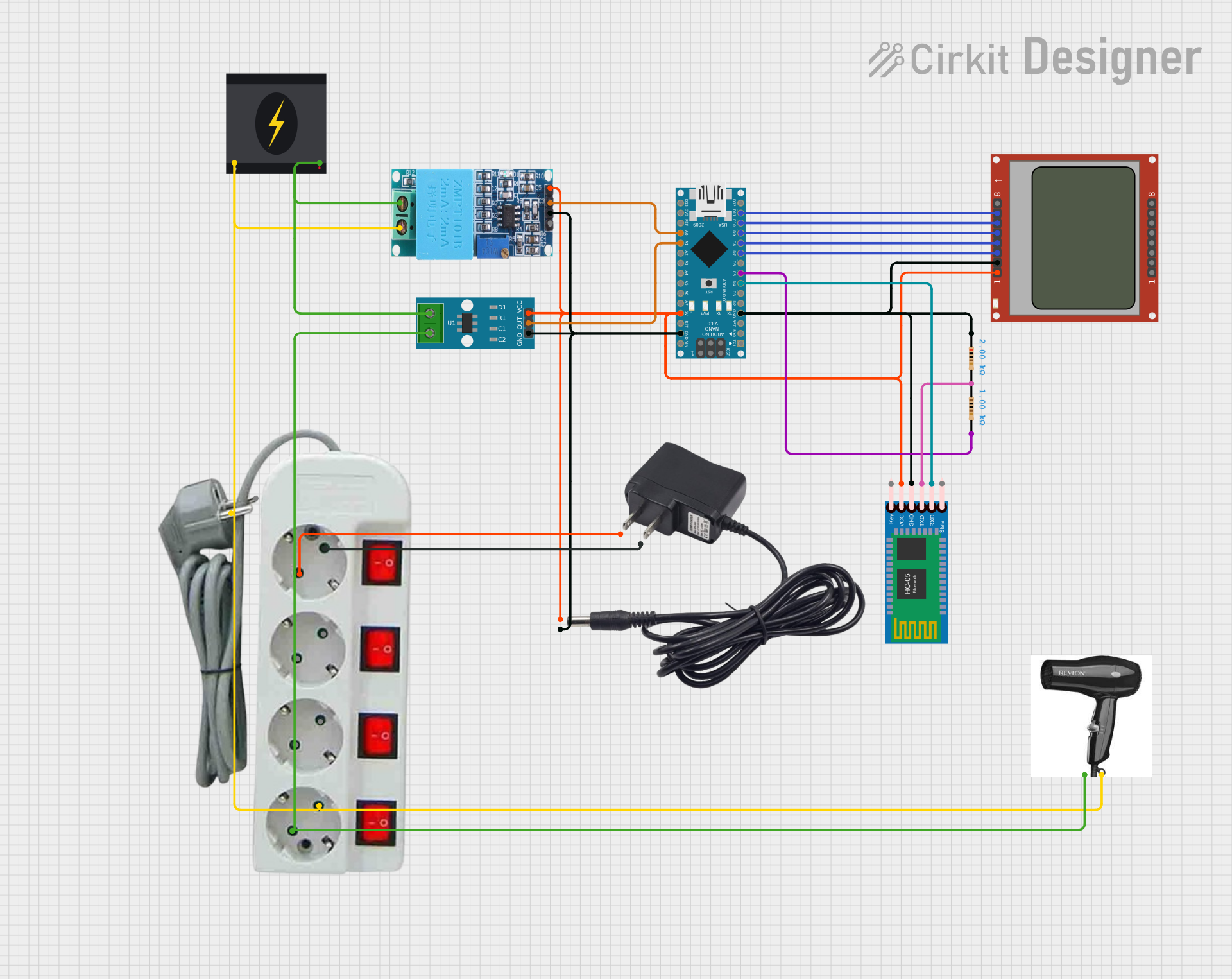
Explore Projects Built with Wattmeter
Common Applications and Use Cases
- Monitoring energy consumption in residential and industrial setups
- Measuring power output of renewable energy systems (e.g., solar panels)
- Testing and analyzing electrical loads in laboratories
- Integration into IoT systems for real-time power monitoring
- Educational purposes for understanding power measurement principles
Technical Specifications
The PZEM-051 Wattmeter comes with the following technical specifications:
| Parameter | Value |
|---|---|
| Voltage Range | 80V to 260V AC |
| Current Range | 0A to 100A |
| Power Range | 0W to 22kW |
| Frequency Range | 45Hz to 65Hz |
| Accuracy | ±1% |
| Communication Interface | UART (TTL level) |
| Power Supply | Self-powered (via measured circuit) |
| Operating Temperature | -10°C to 60°C |
| Dimensions | 70mm x 40mm x 30mm |
Pin Configuration and Descriptions
The PZEM-051 Wattmeter has the following pin configuration:
| Pin Name | Description |
|---|---|
| V+ | Positive voltage input for the measured circuit |
| V- | Negative voltage input for the measured circuit |
| I+ | Positive current input (connected to the load side of the current transformer) |
| I- | Negative current input (connected to the source side of the current transformer) |
| TX | UART Transmit pin for communication |
| RX | UART Receive pin for communication |
| GND | Ground pin for UART communication |
Usage Instructions
How to Use the Component in a Circuit
Connect the Voltage Input:
- Connect the
V+andV-pins to the AC or DC circuit you want to measure. Ensure the voltage is within the specified range (80V to 260V AC).
- Connect the
Connect the Current Transformer:
- Use the provided current transformer (CT) to measure current. Connect the
I+andI-pins to the CT as per the polarity markings.
- Use the provided current transformer (CT) to measure current. Connect the
Communication Setup:
- If you need to interface the wattmeter with a microcontroller (e.g., Arduino), connect the
TX,RX, andGNDpins to the corresponding UART pins on the microcontroller.
- If you need to interface the wattmeter with a microcontroller (e.g., Arduino), connect the
Power On:
- The wattmeter is self-powered and will start operating as soon as it is connected to the measured circuit.
Read Measurements:
- Use the UART interface to read voltage, current, power, and energy data. The data can be processed and displayed on an external device, such as an LCD or a computer.
Important Considerations and Best Practices
- Safety First: Always ensure the circuit is powered off before making connections to avoid electric shock or damage to the wattmeter.
- Current Transformer Polarity: Ensure the CT is connected with the correct polarity to avoid incorrect readings.
- UART Communication: Use a level shifter if interfacing with a 5V microcontroller, as the wattmeter operates at TTL levels.
- Calibration: For accurate measurements, periodically calibrate the wattmeter as per the manufacturer's instructions.
- Environmental Conditions: Avoid using the wattmeter in extreme temperatures or high-humidity environments.
Example: Interfacing with Arduino UNO
Below is an example code to interface the PZEM-051 Wattmeter with an Arduino UNO:
#include <SoftwareSerial.h>

// Define RX and TX pins for SoftwareSerial
SoftwareSerial wattmeterSerial(10, 11); // RX = Pin 10, TX = Pin 11

void setup() {
  Serial.begin(9600); // Initialize Serial Monitor
  wattmeterSerial.begin(9600); // Initialize communication with PZEM-051

  Serial.println("PZEM-051 Wattmeter Interface Initialized");
}

void loop() {
  // Request data from the wattmeter
  wattmeterSerial.write(0xB0); // Example command to request data (refer to datasheet)

  // Wait for response
  delay(100);

  // Check if data is available
  if (wattmeterSerial.available()) {
    Serial.print("Wattmeter Data: ");
    while (wattmeterSerial.available()) {
      // Read and print each byte of data
      Serial.print(wattmeterSerial.read(), HEX);
      Serial.print(" ");
    }
    Serial.println();
  }

  delay(1000); // Wait 1 second before the next request
}
Notes:
- Replace the
0xB0command with the appropriate command as per the PZEM-051 datasheet. - Ensure the RX and TX pins are correctly connected to the wattmeter.
Troubleshooting and FAQs
Common Issues and Solutions
No Data Output on UART:
- Cause: Incorrect wiring or baud rate mismatch.
- Solution: Verify the TX and RX connections. Ensure the baud rate is set to 9600.
Incorrect Power Readings:
- Cause: Current transformer polarity is reversed.
- Solution: Check and correct the CT connections.
Wattmeter Not Powering On:
- Cause: Insufficient voltage or loose connections.
- Solution: Ensure the voltage input is within the specified range (80V to 260V AC).
Interference in UART Communication:
- Cause: Long UART cables or noisy environment.
- Solution: Use shorter cables and shielded wires for UART communication.
FAQs
Q1: Can the PZEM-051 measure DC power?
A1: No, the PZEM-051 is designed specifically for AC power measurement.
Q2: What is the maximum current it can measure?
A2: The wattmeter can measure up to 100A using the provided current transformer.
Q3: Can I use this wattmeter with a Raspberry Pi?
A3: Yes, you can use the UART interface to connect the wattmeter to a Raspberry Pi. Ensure proper voltage level shifting if required.
Q4: How do I reset the energy counter?
A4: Refer to the manufacturer's datasheet for the specific UART command to reset the energy counter.
This concludes the documentation for the PZEM-051 Wattmeter. For further details, refer to the manufacturer's datasheet or contact technical support.